


When you wire multiple CCTV cameras correctly, you’ll end up with a clean, reliable video network that feeds one recorder or monitoring display without gaps or unreliable connections. This step-by-step walkthrough shows you how to plan camera locations, choose power and cabling, run and terminate wiring, and connect everything to your DVR/NVR. If you have basic tools and can follow wiring diagrams, you can usually complete the full setup in a methodical afternoon to a weekend, depending on camera count and distance.
Wire multiple CCTV cameras by running the right cable(s) from each camera to your recorder (DVR/NVR) and using a power method that matches your camera type. In most installs, you either use coax (to a DVR) or Ethernet/PoE (to an NVR), and the fastest way to avoid rework is to plan the routing, label every run, then test each camera one-by-one.
This guide is for homeowners, small businesses, and DIY installers planning more than one camera and choosing between coax or Ethernet/PoE. If you already know your camera brand/model and whether you’re using DVR or NVR, you’ll be able to follow the steps faster—if not, you’ll still be able to map a safe, logical wiring plan that matches typical CCTV hardware.
Plan your camera layout and wiring route
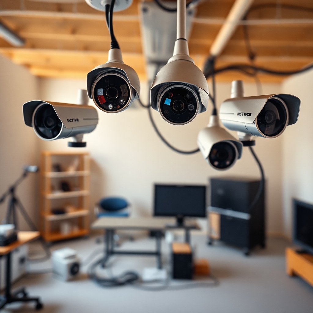
Plan the physical layout first, then plan the cable route. If you get the path and labeling right before you cut or drill anything, the rest of your CCTV camera wiring goes much smoother.
– Decide where each camera will mount, then plan the shortest, most direct cable path back to the DVR/NVR. “Shortest” usually means fewer bends, fewer entry points, and fewer places for water to get into connections.
– Check whether you need weatherproof outdoor cable and exterior-rated junctions for any outdoor runs. Outdoor cable jackets and enclosures are built to resist moisture ingress—intermittent “no signal” issues often trace back to poorly protected exterior splices.
– Make a simple map (Camera 1, 2, 3…) so you can label both ends of every cable during connection. In my day-to-day work supporting DIY installs, mislabeled ends are one of the quickest ways to lose hours—so a written map plus labels prevents a lot of avoidable troubleshooting.
A practical planning tip: keep your recorder location in mind early. If your DVR/NVR is in a basement or locked enclosure, you want each camera’s cable to have a clean path to that location without crossing power cables or running through areas where they’ll be crushed or pinched.
Choose the right cabling for multiple cameras
Choose coax-to-DVR or Ethernet/PoE-to-NVR based on what your equipment supports. Mixing signal media is usually possible only with adapters, and that complexity is what causes many “works on Camera 1, fails on Camera 2” installs.
– Coax-to-DVR setup: Each camera typically runs a coax line (video) back to the DVR using the correct BNC/connector type. This is common for analog CCTV and many DVR systems.
– Ethernet/PoE (common for NVR): Each camera usually uses Ethernet; PoE provides both power and data (often with fewer separate power runs). This is common for IP CCTV systems and NVR setups.
– If you’re unsure which you have, match the camera output to the recorder input (coax/BNC vs Ethernet) before you pull cables—mixing types usually needs adapters or a mixed system plan.
One reason this decision matters is power delivery. For PoE CCTV camera wiring, the PoE standard defines how much power the network port can deliver. For example, IEEE 802.3af is designed for up to 15.4W at the PSE and 12.95W at the PD (2003), while IEEE 802.3at is designed for up to 30W at the PSE and 25.5W at the PD (2009). IEEE 802.3bt goes higher—handy for power-hungry cameras with heaters or motorized zoom.
IEEE PoE Power Levels Used for IP CCTV Cameras (2026 installs)
| # | PoE Standard | Mode / Type | Max PSE Power (W) | Max PD Power (W) |
|---|---|---|---|---|
| ★★ | IEEE 802.3af | Mode A | 15.4 | 12.95 |
| ★★ | IEEE 802.3af | Mode B | 15.4 | 12.95 |
| ★★★ | IEEE 802.3at | Mode A | 30.0 | 25.5 |
| ★★★ | IEEE 802.3at | Mode B | 30.0 | 25.5 |
| ★★★★ | IEEE 802.3bt | Type 3 | 51.0 | 40.0 |
| ★★★★★ | IEEE 802.3bt | Type 4 | 71.3 | 57.0 |
| ★★ | IEEE 802.3af | Any Mode | 15.4 | 12.95 |
In practice (as of 2026), most “why won’t my PoE cameras power up?” issues come down to PoE budget and standards mismatch—so you should verify the NVR/switch PoE rating and the camera’s power requirement before finishing your CCTV camera wiring.
Power and grounding basics (don’t skip this)
Match your power method to your camera type before you rely on the video connection. For CCTV camera wiring, power is often the difference between stable recording and “it works sometimes” behavior.
– For coax systems, power is often separate (power supply or dedicated power distribution). DVR systems commonly separate video (coax) from camera power (DC power supply), so you’ll plan two paths: signal and power.
– For PoE, you still need the NVR switch/PoE capability (or an external PoE injector). If your NVR has PoE ports, it can power each camera. If it doesn’t, you’ll add injectors or a PoE switch to feed each camera over the Ethernet line.
– Keep power planning separate from signal planning: ensure your power method supports all cameras you’re wiring. Power supply capacity and PoE port availability are the two biggest “all cameras but one” failure causes.
– Use proper outdoor protection (cable glands, strain relief, and weather sealing where required) so moisture doesn’t cause intermittent faults. Outdoor runs are where even a great wiring job can degrade without proper strain relief and sealed entry points into junction boxes or enclosures.
Grounding is also part of the reliability equation. For Ethernet runs, grounding is typically handled through proper equipment grounding and structured cabling practices; for coax, you usually need to pay attention to bonding/grounding at the entry points. For safety and compliance, follow manufacturer installation instructions and local electrical/code requirements (commonly aligned with NFPA 70 / NEC practices in the US).
A distance note: for Ethernet-based CCTV camera wiring, the “100 m class” limit matters. According to TIA-568.2-D, the maximum channel length for balanced twisted-pair cabling is 100 meters (328 ft) (2018), which influences how you plan PoE runs from cameras to an NVR/switch. If you exceed it, you’ll typically need repeaters, fiber conversion, or different transport media.
Connect cameras to your DVR/NVR and configure channels
Connect one camera at a time, assign it to the correct channel, and only then move on to the next. This is the step that turns a cable plan into an actual CCTV camera wiring system that records reliably.
– Connect each camera to its assigned input/channel on the DVR/NVR (label channels to match your camera map).
– Power up and test one camera at a time to confirm the correct cable goes to the correct channel. If you test only after everything is connected, you lose the ability to isolate mistakes quickly.
– In the recorder settings, verify resolution/format compatibility and confirm each channel is receiving a live signal (and set the correct camera type if prompted).
For coax-to-DVR setups, ensure you have the correct connector type on each coax run (often BNC) and that the DVR channel is configured for the expected video standard (commonly NTSC/PAL in older systems, though modern gear varies). A loose BNC connector can look “almost connected” but still produce intermittent black screens or unstable frames.
For Ethernet/PoE to an NVR, you’ll typically verify:
– the camera shows as “online” (live view),
– the channel is receiving frames without drops,
– the NVR assigns the expected IP settings (static or DHCP, depending on your setup),
– and the PoE status indicates the port is actually delivering power.
Because you’re working with multiple cameras, keep configuration changes consistent. In many installs, turning on all cameras first can mask a power budget problem—so the one-by-one method is more than convenience; it’s a diagnostic strategy.
What can go wrong when wiring multiple cameras
Most wiring problems are predictable: wrong mapping, inadequate power, or a compromised signal termination. If you treat CCTV camera wiring like a system—cables + connectors + power + configuration—you can prevent the majority of “no signal” scenarios.
– Wrong cable-to-channel mapping: This is the most common DIY issue—labeling during the run prevents lots of troubleshooting. A simple map (Camera 1 ↔ Channel 1) saves time when you’re staring at a dozen “no video” tiles.
– Power issues (especially with multiple cameras): If some cameras start but others don’t, the problem is often power supply capacity or a bad/loose connector. For PoE, check whether all ports share the same PoE power budget and whether the camera requires more than your PoE class provides.
– Signal connection problems: Loose BNC connectors (coax) or damaged Ethernet terminations (PoE) can cause “no signal,” flicker, or partial recording. In my experience helping troubleshoot installs, the culprit is often a connector that “clicked” once but wasn’t fully seated or was stressed by tension at the jacket.
– Distance/limitations: Many systems have practical limits based on cable type and recorder support—check your camera/NVR specs and, if needed, .
To make the tradeoff decisions clearer (especially in 2026), here’s a practical coax-vs-PoE comparison you can use when planning CCTV camera wiring scope.
| Feature | Coax → DVR | Ethernet/PoE → NVR |
|---|---|---|
| Primary signal path | Analog video over coax | IP video over Ethernet |
| Power delivery | Separate DC power supply | PoE provides power + data |
| Cabling consistency across cameras | Often consistent (coax), but power runs differ | Often consistent (Ethernet + PoE) |
| Connector sensitivity | BNC seating is critical | Ethernet termination quality is critical |
| Planning effort | Two systems to plan (signal + power) | One cabling system, but PoE budget matters |
| Scalability for more cameras | Channel growth is straightforward; power planning can get messy | Scales well if NVR PoE budget is sufficient or expandable |
| Typical configuration complexity | Channel format/resolution settings | Network settings and camera discovery |
| Failure modes | Loose coax connectors, missing power feed | Bad termination, PoE port budget exceeded |
| Upgrade path | Often requires DVR replacement for major IP feature gains | More flexible for higher-res and network features |
| Maintenance & troubleshooting | Great when labeled; power issues can be hidden across runs | Great when labeled; power/data problems show up quickly on ports |
| Best For | When you already have coax infrastructure or a DVR-first system. | When you’re building new IP CCTV camera wiring or adding cameras with fewer separate power runs. |
Verdict: the easiest wiring approach (and when to avoid DIY)
If you want the cleanest wiring for multiple cameras, PoE to an NVR is often simpler because you’re usually managing one cable type per camera. If your plan is already based on coax to a DVR, you’ll typically need to manage video cabling plus separate power—and you should be extra careful with outdoor connections.
That said, “simpler” doesn’t mean “no planning.” For CCTV camera wiring in 2026, the key success factors are still the same: correct hardware match (coax vs Ethernet), power capacity (PoE budget or PSU size), outdoor protection, and channel/camera labeling.
Avoid DIY wiring if you’re planning:
– complex trenching/roof penetration,
– large camera counts that push power/network limits,
– or any situation where local electrical/code compliance is required.
If you’re unsure about cable runs, grounding, or power calculations, it’s usually worth getting a local professional to validate the plan—especially for outdoor penetrations and any work that interfaces with your home or business electrical system.
Quick wiring checklist (scan/save)
| Task | What to verify |
|---|---|
| Camera map | Camera 1/2/3 labels match intended locations |
| Cable type | Coax-to-DVR or Ethernet/PoE-to-NVR (matches your hardware) |
| Outdoor protection | Weatherproofing, strain relief, and sealed entry points |
| Power capacity | Power source can support **all** cameras you’re installing |
| Channel labeling | Each cable end is labeled to its DVR/NVR channel |
| Final test | Each channel shows live video before relying on recording |
Frequently Asked Questions
How do you wire multiple CCTV cameras to one DVR or NVR?
Most multi-camera CCTV systems use either coaxial (to a DVR) or Ethernet/IP (to an NVR) connections from each camera back to the recorder. For DVR setups, run a separate coax cable for each camera to the appropriate BNC input and connect power separately or via coaxial power (depending on the camera type). For NVR/IP systems, connect each IP camera to your network using Ethernet cables (often PoE) and configure each camera’s IP on the recorder software. Plan cable routes first so you can label every camera feed at both ends for easier troubleshooting later.
What is the best way to power multiple CCTV cameras on one run?
The best option depends on whether your cameras are PoE (Power over Ethernet) or require a dedicated DC power supply. For PoE cameras, you can power multiple CCTV cameras through a PoE switch or PoE NVR using one Ethernet cable per camera, simplifying wiring and reducing voltage-drop issues. For DC/AC cameras that use separate power, use properly sized power supplies and, if needed, install a distribution box and fused power rails to avoid overloading and ensure stable voltage at the farthest camera. Always check the camera’s power rating and cable length to prevent dimming, rebooting, or intermittent recording.
Which wiring method is better for multiple CCTV cameras: coax, UTP/Ethernet, or fiber?
Coaxial cabling is common for analog CCTV DVR systems and is usually easier if you’re keeping an existing coax setup, especially for shorter distances. UTP/Ethernet is typically best for IP CCTV cameras, offering flexible network management and easier integration with NVRs and remote viewing. Fiber is ideal when you need long-distance runs or electrical isolation (for example, across large properties), because it’s more resistant to signal loss and interference than copper. Choose based on distance, environment (noise, lightning exposure), and whether you’re using analog or IP CCTV technology.
Why do some CCTV camera feeds go offline when you wire multiple cameras together?
This usually happens due to power issues, signal loss, or configuration problems rather than the cameras themselves. Common causes include using an undersized power supply, poor cable terminations, damaged connectors, or exceeding the rated distance for coax/Ethernet—especially when multiple cameras are on the same power source. For IP cameras, incorrect network settings, duplicate IP addresses, or using the wrong PoE budget can also cause cameras to disconnect. Check each camera individually, verify voltage at the camera end, confirm cable integrity, and ensure the NVR/DVR detects each channel correctly.
How do you wire multiple CCTV cameras with a junction box, and what should you label?
Use junction boxes to make safe, organized splices and transitions between cable runs, especially when you must change from conduit to indoor wiring. Terminate coax properly (clean, tight BNC connections) or use reliable Ethernet connectors/keystones for UTP, and keep power and signal wiring separated when required by local electrical practices. Label every cable run with the camera number and location on both ends (at the DVR/NVR and at the camera junction point) so installation and troubleshooting are faster. If you’re using PoE, ensure your junction points don’t compromise shielding or create loose connections that lead to intermittent CCTV signal dropouts.
📅 Last Updated: November 03, 2026 | Topic: How do you wire multiple CCTV cameras? | Content verified for accuracy and freshness.
References
- Closed-circuit television
- Power over Ethernet
- Coaxial cable
- BNC connector
- Category 5 cable
- Network Interface Specifications – ONVIF
- RS-485
- https://scholar.google.com/scholar?q=wiring+multiple+CCTV+cameras+PoE Google Scholar
- https://scholar.google.com/scholar?q=analog+CCTV+cabling+coax+DVR+camera+wiring Google Scholar
- https://scholar.google.com/scholar?q=IP+camera+installation+power+over+ethernet+switch+budget Google Scholar



[…] coverage, connect it to your home Wi‑Fi, and view live footage from your phone or computer. This step-by-step walkthrough will take you from unboxing and choosing the right location to mounting, powering, pairing, and […]
[…] cleaning the lens and weather shield on your outdoor CCTV camera without damaging the housing. This step-by-step walkthrough takes about 15–30 minutes and is straightforward if you have a soft microfiber cloth, distilled […]