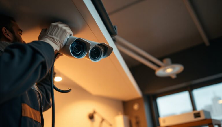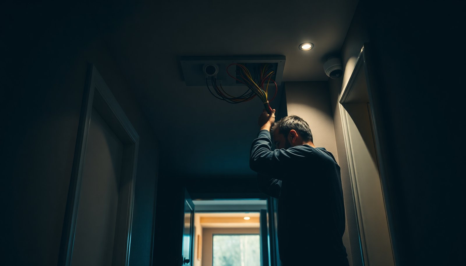

Properly wiring multiple CCTV cameras requires routing power and video (or data) runs correctly so each camera gets stable power and a clean signal to the recorder. You can usually complete a straightforward multi-camera install in a few hours, but it becomes more involved with long cable lengths, mixed cable types, or existing conduit. Gather your DVR/NVR, compatible cable, correct connectors/termination tools, a rated power supply or PoE switch, and a multimeter, then follow a clear step-by-step path from layout to testing.
Wire multiple CCTV cameras by using the wiring type that matches your system (analog-to-DVR or IP-to-NVR/PoE switch) and planning power and cable routes before you run anything. This article shows the order to wire, connect, and test so each camera gets both a stable power feed and a clean video signal.
If you’re adding more than one camera (front door, driveway, back yard, etc.), the main challenge isn’t “more cameras”—it’s keeping the connections, power method, and recorder inputs consistent across the whole setup.
Confirm whether you’re installing analog or IP cameras
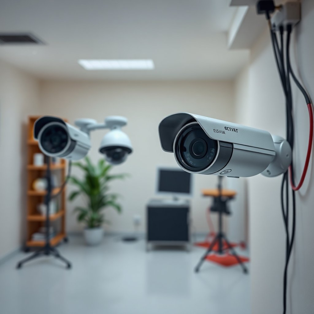
If you confirm analog vs IP up front, the rest of the wiring process becomes straightforward and repeatable. The “right” approach is different: analog CCTV uses coax/BNC-style video into a DVR plus (often) dedicated power, while IP CCTV uses Ethernet into an NVR or a PoE switch for both data and power.
First, identify the recorder you already have (DVR vs NVR), because that determines how each camera must connect. Analog systems typically output a video signal that terminates on specific DVR channels (often labeled CH1, CH2, etc.) and usually use coax cable with BNC connectors. IP systems output network video and connect via Ethernet to an NVR port or to a PoE switch that supplies power and carries data over the same cable.
A second key confirmation is each camera’s power method. Analog cameras generally need separate DC power adapters (or a power supply with a distribution block), whereas IP cameras are commonly powered by PoE (Power over Ethernet) according to an IEEE standard. According to IEEE 802.3af (PoE), PoE Type 1 equipment delivers up to 15.4W at the power sourcing equipment (PSE) and typically supplies about 12.95W at the powered device (PD). According to IEEE 802.3at (PoE+), Type 2 delivers up to 30W at the PSE and about 25.5W at the PD.
If you have a mixed system, do not “figure it out later.” Confirm each camera’s required input and power method in its manual—double-check the exact video interface (analog coax output vs IP Ethernet output) and the required power voltage/current. As of 2026, many installation problems still trace back to mixing signal types or mis-matching PoE availability on a switch.
Analog-to-DVR vs IP-to-NVR/PoE at a glance
- Analog (coax → DVR)
- Pros: Simple channel mapping; fewer network variables; often easier for legacy systems.
- Cons: Coax runs can be less flexible; lower typical video detail than modern IP; recorder upgrades may require rewiring.
- IP (Ethernet → NVR / PoE switch)
- Pros: One cable carries data + power (with PoE); easier remote access; scaling options with NVR/managed switch ports.
- Cons: Network settings (DHCP/static IP) can complicate onboarding; Ethernet distance and switch capabilities still matter.
Plan cables, power, and recorder ports before running wire
Planning first is what keeps multi-camera CCTV wiring from turning into a troubleshooting project later. You should decide camera locations, cable routes, power sourcing, and recorder inputs while the system is still on paper—before you open walls or pull exterior cable.
Start by mapping each camera location to a specific recorder input:
– Analog: map each camera to a specific DVR channel number (for example, “front door → CH1”).
– IP: map each camera to an NVR port or to a PoE switch port number (for example, “driveway → PoE Switch Port 3” and then “NVR/management VLAN → same network plan”).
Next, verify capacity. If your analog DVR has 8 channels, you can’t wire 10 analog cameras to it—those extra connections won’t have a place to terminate. If your IP NVR has 8 camera licenses or ports (depending on model), you must also account for PoE switch port capacity if you’re not feeding cameras directly into the NVR.
Now calculate power with the exact specs for your cameras and PoE switch model. Do not guess. PoE switches also have power budgets (the total available watts across all ports), and those limits control how many cameras can run simultaneously at full load (heaters/IR illuminators during night can increase draw). For PoE distance planning, remember that copper Ethernet segments are typically limited to 100 meters (328 feet). According to IEEE 802.3, 10/100/1000BASE-T copper links use a maximum segment length of 100m under standard conditions. This is one of the most practical “hard limits” for IP CCTV wiring.
Use this planning step to build your power math:
– Add each camera’s power draw from its datasheet (watts).
– If using PoE, confirm the PoE class/standard each camera supports and ensure the switch provides enough total watts across all active ports.
– If using separate adapters for analog cameras, confirm the adapter’s output voltage/current matches the camera’s requirement and that the adapter can handle peak usage (especially if the camera has motorized parts or high-IR LEDs).
To keep your wiring plan auditable, capture these inputs in a simple table before you run a single cable. Below is a quick reference that helps with IP camera planning: copper Ethernet speed classes and typical maximum reach.
Copper Ethernet Runs Commonly Used for IP CCTV (Typical Limits)
| # | Ethernet link | Typical min cable | Throughput | Max copper reach |
|---|---|---|---|---|
| 1 | 10BASE-T | Cat3 | 10 Mb/s | 100 m |
| 2 | 100BASE-TX | Cat5 | 100 Mb/s | 100 m |
| 3 | 1000BASE-T | Cat5e | 1 Gb/s | 100 m |
| 4 | 2.5GBASE-T | Cat5e | 2.5 Gb/s | 100 m |
| 5 | 5GBASE-T | Cat5e | 5 Gb/s | 100 m |
| 6 | 10GBASE-T (Cat6a) | Cat6a | 10 Gb/s | 100 m |
| 7 | 10GBASE-T (Cat6) | Cat6 | 10 Gb/s | 55 m |
How to read this table in your CCTV wiring plan
For IP CCTV cameras, the 100m “ceiling” is usually the first constraint to validate, especially when you plan to power cameras via PoE. In practice, your camera’s actual negotiated speed depends on cable grade, terminations, and link negotiation—so treat these max reach numbers as the boundary you engineer toward, not toward which you “assume you’ll land.”
Run cabling and weatherproof connections correctly
Neat, weather-ready cabling is what protects your CCTV video signal after the first rainstorm. When you run outdoor wire, your goal is to prevent water intrusion, strain damage, and interference that can cause flicker, dropouts, or “no signal” symptoms later.
Plan physical routes that keep cable protected:
– Use conduit where feasible (especially where cables cross paths with landscaping, vehicles, or sharp edges).
– Choose outdoor-rated cable with an appropriate jacket for UV exposure and direct burial/condensation-prone locations.
– Secure cable runs with proper fasteners and strain relief so connectors don’t bear mechanical load.
Weatherproofing is not just “wrapping it with tape.” Use junctions and weather-rated connectors where cables meet—especially for exterior runs. Moisture entering a connection box can corrode terminations and degrade performance over time. For outdoor terminations, follow the component manufacturer’s instructions for sealing and torque—loose connections can mimic “power problems” because PoE and video links can fail intermittently.
Labeling is the difference between a clean install and a mystery. Label both ends of every cable at install time so you can match camera location to DVR/NVR input during wiring. If you plan to add cameras later, labels also make future expansion far cheaper than “trace-and-test” work.
Terminate and connect video (and power) to the right device
Connecting the right signal to the right port prevents the most frustrating failure mode: “everything is connected but nothing works.” Termination discipline matters, because miswired channels or mismatched connector types can look correct at a glance while still producing no video.
For analog systems, connect each camera’s video lead to the correct DVR channel and confirm the connector type matches the camera/DVR ports (commonly BNC-style interfaces). Then route and connect power using the camera’s specified voltage and current. If you’re using a shared power supply, verify distribution wiring is consistent and protected (for example, with proper fusing and a clean grounding strategy where applicable).
For IP/PoE systems, connect each camera to the PoE switch (or PoE NVR port). Then verify your NVR network plan:
– If your NVR expects DHCP, make sure the network can assign addresses reliably.
– If you use static IP addressing, confirm each camera’s IP, subnet mask, gateway, and credentials exactly match your NVR’s discovery/setup method.
Grounding and shielding matter for long outdoor runs. For IP systems, use manufacturer-recommended cable types and follow guidance on shielding/termination to reduce interference. For analog systems, coax shielding helps maintain video integrity over distance and reduces noise pickup from nearby power conductors.
Configure each camera and verify signal one by one
You get the fastest “it works” milestone by validating each camera sequentially, not simultaneously. Start with one camera: confirm it powers up and confirm live video appears before moving on to the next camera.
For analog cameras, live video verification usually means confirming the correct channel displays an actual image (not just “signal detected”). For IP cameras, verify both connectivity and video decoding in the NVR interface. If the system uses network settings, apply the supported method consistently:
– DHCP: ensure the NVR can discover cameras and that reservations or stable leases are configured where needed.
– Manual IP: record the IP address per camera and avoid duplicates across the network.
Adding remaining cameras should follow the same repeatable order: power check → link check → live video check. This order helps isolate whether problems are power delivery, cabling/termination, or recorder configuration. It also reduces downtime because you can fix one camera without disrupting working channels.
In 2026, many installers also document camera assignments (camera name ↔ port number ↔ IP address ↔ channel number). That documentation pays off during maintenance and when someone asks, months later, “Which cable is the driveway camera?”
What can go wrong (and how to prevent it)
Most CCTV wiring failures come from power instability, termination errors, distance limits, or system-mixing. If you treat these as design constraints—rather than “oops” moments—you can prevent the majority of field troubleshooting.
Common issues and prevention tactics:
– Power issues: Cameras that intermittently go offline are often underpowered, using the wrong adapter, or tied to an inadequate power source. For PoE, also confirm your switch budget supports simultaneous operation.
– Bad termination: Loose or incorrectly matched connectors can look “fine” until you add more cameras and the system draws higher load or begins to negotiate links differently.
– Distance limits: Every cable/power method has limits—if you exceed them, you may get dim video, dropouts, or no signal (). For IP/PoE, plan around the 100m copper segment limit noted above; for analog coax, distance varies by cable type and video format.
– Mixing standards: Connecting an IP camera to an analog DVR input (or vice versa) won’t work. Double-check camera type and recorder compatibility before final termination.
– Network conflicts (IP setups): If multiple devices end up with the same settings, you’ll see connection failures even with perfect cabling. Avoid overlapping IP ranges and confirm DHCP reservations/static IP entries are unique.
Quick wiring checklist (scan before you start)
– [ ] Confirm analog vs IP, and confirm the recorder type (DVR vs NVR)
– [ ] Plan cable routes and label both ends of every run
– [ ] Ensure enough inputs/ports for all cameras
– [ ] Verify power method per camera (adapter vs PoE) and total power budget ()
– [ ] Use weather-rated cable, conduit, and outdoor connectors for exterior runs
– [ ] Connect video (and PoE/power) to the correct channels/ports
– [ ] Test one camera at a time before finishing the rest
A proper multi-camera CCTV wiring job comes down to matching camera type to the correct wiring and power method, planning ports and power before running cables, and testing camera-by-camera once everything is connected. If you’re unsure whether your cameras are analog or IP (or what power they require), pause and verify in the manuals before you connect anything—doing that upfront saves hours of troubleshooting.
Frequently Asked Questions
How do I properly wire multiple CCTV cameras to a single DVR/NVR?
Start by confirming whether your setup is coax (CVBS/analog) or IP (Ethernet/PoE), because the wiring method changes completely. For analog CCTV, run a coax cable from each camera to the DVR’s corresponding channel and use proper BNC terminations with RG59/RG6 rated cable. For IP CCTV, connect each camera to a PoE switch or PoE injector using Ethernet, then plug the NVR/DVR into your network. Label each cable by camera location and channel number to prevent miswiring during installation.
What is the best way to power multiple CCTV cameras without causing voltage drop?
Plan power distribution based on camera distance and total load, since long runs can cause flickering, rebooting, or weak IR performance. For 12V DC analog cameras, calculate voltage drop and consider thicker gauge wire or local power supplies for cameras far from the power source. For IP CCTV, use PoE (802.3af/at or suitable standards) and place the PoE switch/injector closer to clusters of cameras. Always match the camera’s required voltage and power budget and avoid mixing incompatible power adapters.
Which cable type should I use when wiring multiple CCTV cameras?
Use RG59 or RG6 coax for most analog CCTV runs, choosing the correct shielding level to reduce interference from power lines and motors. For IP CCTV, use Cat5e or Cat6 Ethernet and ensure the terminations are solid (crimped properly, not loose) for reliable video. If you’re in a noisy environment, prioritize shielded twisted pair (STP) Ethernet and keep cable runs separated from mains wiring. Using the wrong cable type can lead to signal loss, poor picture quality, or intermittent disconnects.
Why do my CCTV cameras lose video or show interference after wiring multiple units?
Most issues come from inadequate shielding, loose connectors, wrong termination, or exceeding recommended cable lengths for the signal type. For analog CCTV, ensure BNC connectors are properly seated and use appropriate terminators if required by your DVR setup. For IP CCTV, verify correct network configuration, check link speed, and inspect Ethernet cabling for damage or poor crimping. Also confirm you’re using correct power wiring—unstable power commonly causes rebooting and “no signal” conditions.
How do I route and secure CCTV camera wiring for multiple camera locations?
Run cables through protected paths such as conduit, junction boxes, and cable trays, especially where they cross driveways, rooftops, or areas exposed to weather. Keep power cable runs separated from CCTV data/video lines to reduce electrical noise and interference, and avoid sharp bends that can damage insulation or internal conductors. Use cable clamps and strain relief so connectors aren’t stressed, and label both ends of each cable for easier troubleshooting. For outdoor installs, use weather-rated connectors and consider surge protection and proper grounding to protect multiple camera circuits.
📅 Last Updated: November 03, 2026 | Topic: How do I properly wire multiple CCTV cameras? | Content verified for accuracy and freshness.
References
- Closed-circuit television
- Power over Ethernet
- Coaxial cable
- Structured cabling
- RS-485
- IEEE SA – IEEE 802.3af-2003
- IEEE SA – IEEE 802.3at-2009
- https://scholar.google.com/scholar?q=how+to+wire+multiple+ip+cameras+poe+installation Google Scholar
- https://scholar.google.com/scholar?q=analog+cctv+wiring+multiple+cameras+coax+termination Google Scholar
- https://scholar.google.com/scholar?q=ptz+cctv+rs-485+wiring+installation+guide Google Scholar