
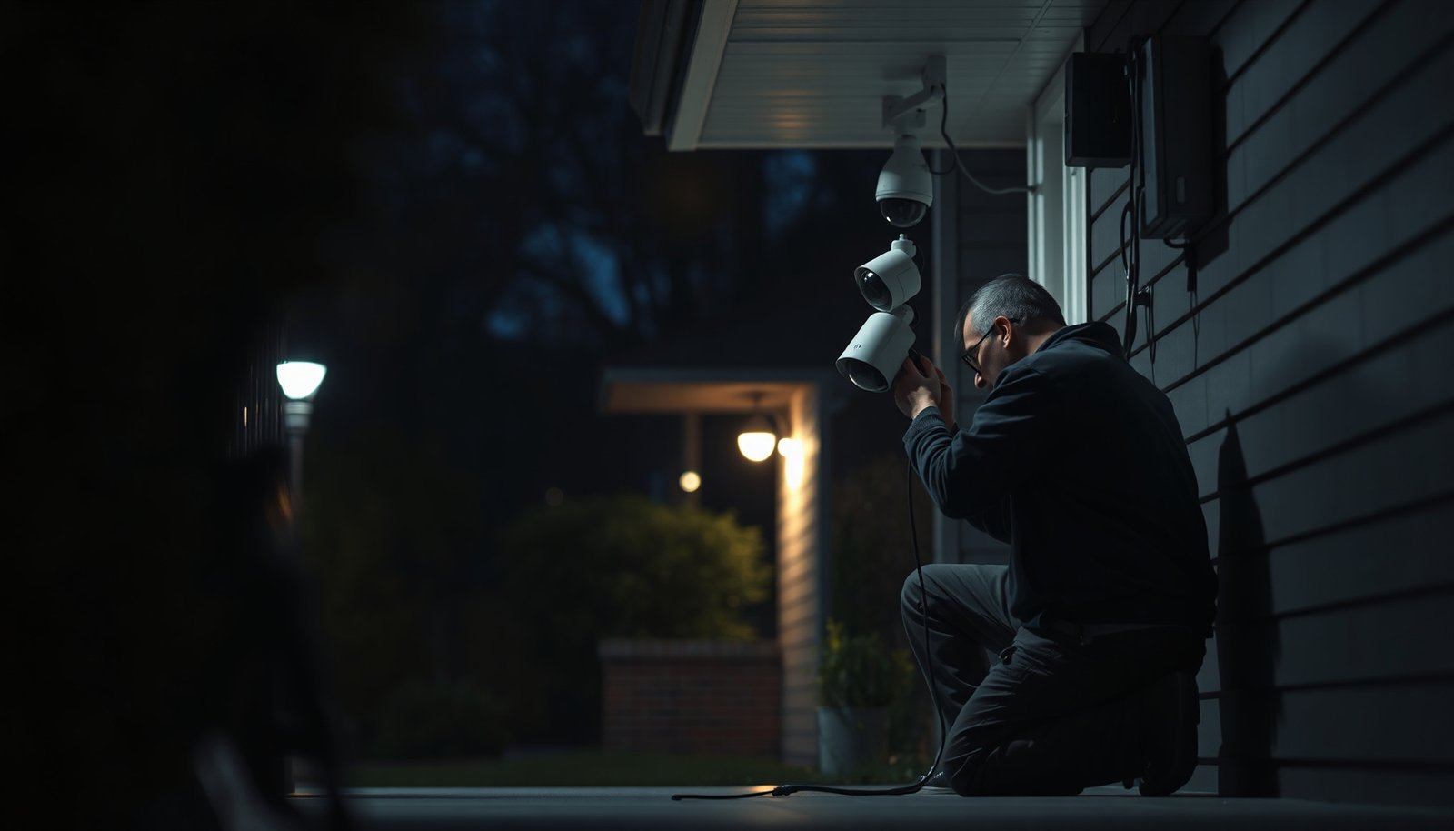

Wiring multiple CCTV cameras requires planning the layout, choosing the right cable type and power method for each camera, and then running video and power to the correct junctions and recorder inputs. If you have basic tools, you can usually complete a straightforward multi-camera install in a day or two, while more complex routes may take longer. You’ll need compatible cables (such as coax or Ethernet, depending on the system), proper connectors, a power solution, and access to your DVR/NVR and monitor setup—so start by mapping where each camera will mount and how every run will connect.
Wiring multiple CCTV cameras usually comes down to planning power, choosing the right cabling, and running a clean video/power path to a DVR/NVR (or into a network switch, for IP cameras). Start by deciding whether your system is analog (coax to a DVR) or IP (Ethernet/PoE to an NVR), then map camera locations so you can size cable runs and the power supply correctly. In this guide, you’ll get the practical steps to wire everything in the right order—without guesswork.
If you’re installing more than one camera—around a driveway, warehouse, or home perimeter—this is for you. It applies whether you’re wiring analog CCTV with coax, or wiring IP cameras that often use PoE, and it’s especially useful when you need multiple cameras to feed one central recorder.
Plan your CCTV wiring setup (analog vs IP)
The fastest way to avoid rework is to decide analog vs IP first, then design routes around that choice. Once you know whether your multiple CCTV cameras are coax-based or network-based, you can lock in the recorder connections, cable type, and power strategy before a single wire is pulled.
Decide the system type (analog or IP)
Analog CCTV typically uses coax cable to send video to a DVR (Digital Video Recorder). IP CCTV uses Ethernet (often PoE—Power over Ethernet) to deliver both video and power to an NVR (Network Video Recorder) or to PoE switches. For multiple CCTV cameras, this single decision drives nearly everything else: connector types, power budgeting, and how you confirm each camera feed.
List camera locations and route constraints
Next, list every camera location and the likely cable route back to the recorder. Even with “straight runs,” obstacles like soffits, structural beams, conduit bends, and service entrances can force detours. For multiple CCTV cameras, route planning is also where you prevent future troubleshooting—because poor cable paths often show up as intermittent video long after the walls are closed.
Identify your “central point”
Pick a central point for convergence: the DVR/NVR location, a comms shelf, or a wiring enclosure. This central point is where all multiple CCTV camera cables should logically meet so you can label, test, and manage them without guesswork. If you’re using IP cameras, the central point also typically includes an NVR, an Ethernet switch (if needed), and either PoE switches or PoE injectors.
Quick comparison: analog vs IP for multiple CCTV cameras
The best choice depends on how you scale and how you want to troubleshoot. Here’s a practical comparison that focuses on wiring reality for multiple CCTV cameras.
| Feature | Analog (Coax to DVR) | IP (Ethernet/PoE to NVR) |
|---|---|---|
| Primary cabling | 75Ω coax | Cat5e/Cat6 Ethernet |
| Recorder integration | DVR channels | NVR + network streams |
| Power approach | Power supply/distribution | PoE switch or PoE injectors |
| Setup complexity | Lower (channel mapping) | Higher (IP settings/network) |
| Scalability for multiple CCTV cameras | More DVR channels needed | Port planning + switch capacity |
| Remote access | Often via DVR/bridge | Typically via NVR/network |
| Troubleshooting style | Video presence at channels | Link, PoE, IP discovery, stream health |
| Typical wiring “gotchas” | Connector/termination quality | Power budget + Ethernet terminations |
| Best fit | Simple perimeters | Expanding multi-zone installs |
| Best For | When you want straightforward coax runs | When you want centralized IP control for multiple CCTV cameras |
Power planning for multiple cameras
Power planning is where many multi-camera CCTV builds succeed or fail, because PoE budgets and voltage drop matter. For multiple CCTV cameras, the goal is simple: ensure every camera gets stable power at the end of its cable run—especially during night vision loads and analytics modes.
Match power method to your architecture
Analog setups commonly use a camera power supply (or distribution approach) separate from the DVR coax video path. IP setups usually rely on PoE switches or PoE injectors placed near the recorder/network. If you’re using multiple CCTV cameras, PoE is often cleaner (fewer separate power cables), but only if you design capacity around total draw.
Calculate power needs with headroom
Start with each camera’s required voltage/current (analog) or PoE power class (IP). For IP, PoE standards define maximums; your real draw may be lower, but you still need margin for distance effects and converter losses. According to IEEE 802.3af, PoE at the power source can deliver up to 15.4 W, while the powered device receives up to 12.95 W (2003). For higher-draw cameras, PoE+ matters: according to IEEE 802.3at, the power source can provide up to 30 W with up to 25.5 W available at the powered device (2009).
Account for run length and voltage drop
For analog multiple CCTV cameras, voltage drop over longer runs can reduce performance or cause intermittent issues when IR illumination kicks in. For IP multiple CCTV cameras, power is typically within spec over the standard Ethernet segment, but still plan the total PoE budget and avoid running “at the limit” if the installer environment is variable.
Choose one central supply vs multiple local supplies
Centralizing power is often convenient at the recorder location, but it increases the effect of long distribution distances. Local supplies can reduce voltage drop and simplify troubleshooting for multiple CCTV cameras, though it may add extra enclosures and wiring points. If you’re unsure, design for the longest camera run first—because the “worst camera” usually determines how much headroom you need.
Choose the right cables and connectors
Choosing the right cable is less about brand preference and more about meeting the physical requirements of your environment and signal type. For multiple CCTV cameras, cable choice directly impacts picture stability, PoE reliability, and resistance to moisture, UV exposure, and interference.
Analog CCTV: coax type and termination plan
Analog CCTV wiring uses coax—typically 75Ω cable—terminated correctly for the DVR’s video inputs and the camera end. The termination method matters because multiple CCTV cameras can all be “working” in theory while one bad connector creates rolling snow, ghosting, or a complete channel loss. Plan the connectors/terminations before you run cable, not while you’re halfway through an enclosure.
IP CCTV: Ethernet rating, port matching, and weatherproofing
For IP cameras, use Ethernet cabling rated for your installation environment (for example, outdoor-rated if exposed). Make sure your terminations match the camera and switch/NVR port type, and ensure outdoor junctions are sealed so condensation doesn’t creep into connectors. For multiple CCTV cameras, poor sealing is a common reason feeds degrade over months, not immediately.
Plan junctions, weatherproof boxes, and strain relief
At every outdoor transition—pole, soffit, conduit termination—use appropriate weatherproof junction boxes and strain relief. Multiple CCTV cameras suffer when cable ends are left exposed or when a connector bears mechanical load. A clean install uses enclosures where water can reach the path and strain relief where movement is possible (like at camera mounts).
Ethernet/Fiber Cable Options for IP CCTV (Maximum Certified Reach & Throughput)
| # | Cable type | Max bandwidth / rating | Typical max run (meters) | Max throughput |
|---|---|---|---|---|
| 1 | Cat5e U/UTP (4-pair copper) | 100 MHz | 100 | 1 Gbps ★★☆☆☆ |
| 2 | Cat6 U/UTP (4-pair copper) | 250 MHz | 100 | 1 Gbps ★★☆☆☆ |
| 3 | Cat6a U/UTP or F/UTP | 500 MHz | 100 | 10 Gbps ★★★★☆ |
| 4 | Cat7 (typically shielded) | 600 MHz | 100 | 10 Gbps ★★★★☆ |
| 5 | Cat8 (short-reach copper) | 2000 MHz | 30 | 25 Gbps ★★★★★ |
| 6 | OM3 multimode fiber (9/125) | 10Gbps class | 300 | 10 Gbps ★★★★☆ |
| 7 | OS2 single-mode fiber (9/125) | Long-haul class | 10,000 | 10–100 Gbps ★★★★☆ |
Run the video and power cabling to the recorder
The right sequence is “route → label → connect at the recorder after you verify each path,” not “connect everything first.” For multiple CCTV cameras, tidy routing and end-to-end labeling are what make future troubleshooting fast rather than guesswork.
Route cables with sensible separation
Route cables from each camera location back to the recorder area while keeping power and signal paths sensible. For multiple CCTV cameras, long parallel runs can increase noise pickup if you mix routing styles poorly (especially in environments with heavy electrical loads). When you must cross, do it intentionally—rather than letting random intersections develop.
Label both ends during installation
Label both ends of each cable as you go. For multiple CCTV cameras, labeling is the difference between “I know exactly which feed failed” and “we have to trace every run.” Use consistent identifiers tied to your camera map (for example, CAM-01, CAM-02) and record them where the DVR/NVR will live.
Leave slack at camera mounts and recorder side
Leave appropriate slack near camera mounts so you can remove a camera without stressing the cable. At the recorder side, leave enough slack to reconnect cleanly without pulling. In multi-camera CCTV wiring, a tight bundle at the recorder is a common cause of connector strain and intermittent channel errors.
Wire analog cameras to a DVR (typical approach)
Connect each analog camera’s coax to the correct DVR channel input. Then connect camera power to the camera’s power leads using your planned supply/distribution method. Verify each cable termination and confirm the DVR recognizes video presence before fully closing walls or enclosures—this step prevents “late surprises” on multiple CCTV cameras.
Wire IP cameras to an NVR (typical approach)
Connect each IP camera via Ethernet to a PoE switch port (or to PoE injectors if you’re not using PoE switching). Then connect the NVR to your network according to your network plan (often within the local LAN). Confirm physical connectivity first—link/PoE status—before you move into IP configuration for multiple CCTV cameras.
Configure camera inputs and confirm signal quality
Configuration is where multiple CCTV cameras become “installed” rather than merely “connected.” The key is to confirm video presence (analog) or stream activation (IP) one camera at a time, using a consistent troubleshooting order.
For analog: confirm channel and picture clarity
Check the DVR channel mapping, then confirm the correct camera appears on that channel. Look for basic image quality: picture clarity, focus, exposure, and whether the channel shows a stable feed rather than intermittent loss. With multiple CCTV cameras, even a correctly wired camera can appear “missing” if it’s assigned to the wrong DVR input.
For IP: assign/confirm IP settings and validate streams
For IP cameras, assign or confirm IP settings using your NVR/software workflow. DHCP (dynamic addressing) can simplify installation, while static IP can improve predictability on complex networks. Once addressed, confirm that each camera appears as an active stream in the NVR interface.
Troubleshoot in the right order (power, then signal/network)
If you see “no video” or unstable streams across multiple CCTV cameras, troubleshoot systematically:
1) cable/termination,
2) power availability (PoE budget or power supply),
3) recorder/channel selection (analog) or NVR settings/IP discovery (IP).
This order matters because network configuration issues won’t matter if the camera never receives stable power.
What can go wrong (and how to avoid it)
Most multiple CCTV camera failures come down to mismatches, insufficient power, or wiring defects that only show up under real load (night mode, IR draw, analytics). If you design for the failure modes below, you drastically reduce downtime during commissioning.
Wrong camera type or port mismatch
One of the most common errors is mixing analog and IP expectations—connecting coax cameras to an IP recorder path or plugging IP cameras into non-compatible ports. For multiple CCTV cameras, double-check recorder model ports and confirm whether each camera is truly analog (coax) or IP (Ethernet). Labeling during the run prevents this expensive mistake.
Insufficient or unstable power delivery
Multi-camera installs fail when the total draw exceeds the PoE switch capacity or when long runs cause voltage issues in analog systems. For IP multiple CCTV cameras, also watch PoE class compatibility: a camera that expects higher power than your PoE switch can supply may boot unreliably or drop during IR activation.
Bad terminations or water ingress
Outdoor junctions and connector issues are a leading cause of intermittent video. Water ingress can create subtle corrosion at terminations that still “sort of work” for weeks. Use rated outdoor junction boxes and weatherproof terminations at every transition for multiple CCTV cameras.
Cable length and interference problems
Very long runs can degrade signal quality, especially when cable routing is inconsistent. For Ethernet links, the standard segment length matters: according to IEEE 802.3, 100BASE-TX specifies a maximum segment length of 100 m for copper Ethernet (1995). If your camera is beyond that, plan for structured extension methods (like media converters or fiber)—don’t “hope the run works” with multiple CCTV cameras.
Network confusion with IP cameras
IP camera issues often look like “missing cameras” even when the physical link is up. Overlapping IP ranges, mismatched VLAN settings, or incorrect NVR discovery settings can stop streams. For multiple CCTV cameras, confirm addressing plan consistency before you assume a hardware fault.
Verdict / tip: wire systematically, not all at once
If you want the most reliable results, wire and test one camera path at a time—power, connection, then video confirmation—before you move to the next. The upside is fewer surprises and faster isolation when multiple CCTV cameras are involved. The downside is you’ll spend more time labeling and doing incremental checks, and IP systems add configuration steps compared to straightforward analog coax runs.
Skip DIY wiring (or get professional help) if you’re dealing with major hidden cabling runs without access, complex network segmentation (VLANs, managed switches), or you can’t safely terminate and verify cabling quality. In those cases, one misstep can create weeks of rework after walls and ceilings are closed.
Analog vs IP “at-a-glance” decision (VS)
Pick the approach that matches your operational needs—wiring time, troubleshooting style, and scalability for multiple CCTV cameras.
| Criteria | Analog CCTV | IP CCTV |
|---|---|---|
| Cabling familiarity | Common | Requires network knowledge |
| Power complexity | Separate supplies | PoE budget planning |
| Commissioning steps | Channel mapping + picture check | Link + IP discovery + stream confirmation |
| Troubleshooting | Video channel presence | Power/link + network settings |
| Scalability | DVR channel-limited | Switch/NVR capacity driven |
| Cable separation concerns | Less IP-layer complexity | Signal + power over same cable |
| Future upgrades | More limited | More flexible (stream settings) |
| Remote viewing | Possible via DVR networking | Typically simpler with NVR networking |
| Typical failure points | Connector/video termination | Power budget + IP config |
| Verdict | Choose when you want simpler wiring and can standardize coax runs | Choose when you want scalable multiple CCTV cameras with centralized IP management |
Quick checklist (scan before you start)
– [ ] Confirm analog vs IP system type (DVR channel vs NVR network/PoE)
– [ ] Choose the correct cable type and connectors for your environment
– [ ] Plan power method (PoE switch/injector or power supply/distribution)
– [ ] Label all cable ends before connecting to the recorder
– [ ] Run camera cables to the recorder location with sensible routing
– [ ] Connect power + video (or Ethernet) and test each camera individually
– [ ] Confirm stable video streams before closing walls/enclosures
Frequently Asked Questions
What steps are needed to wire multiple CCTV cameras?
Start by planning your camera locations, cable routes, and power requirements so you know how each CCTV camera will connect to the NVR/DVR. Install mounting hardware, run the correct cabling (usually coax, Cat5e/Cat6, or fiber), and label both ends to avoid mix-ups. Connect power and video, then configure each camera in the NVR/DVR and verify signal quality by checking live view and signal strength. Finally, tidy the wiring, weatherproof outdoor connections with proper junction boxes, and test recording and remote access.
How do you power multiple CCTV cameras with one system?
Power options depend on the camera type: coax-only CCTV typically needs separate power runs, while IP CCTV with PoE uses a network switch or PoE NVR to deliver power and data. Calculate total wattage for all CCTV cameras and ensure your PoE switch/NVR has enough power (including headroom for startup surges). For mixed setups, you can use PoE for some cameras and injectors/PSUs for others, but keep grounding consistent to reduce noise and outages. Always use the correct gauge power cable and fuse/protect the supply for safety.
Which cable type is best for wiring multiple CCTV cameras over distance?
The best choice depends on distance, environment, and whether you’re using analog (coax) or IP (Ethernet). For short runs and analog CCTV, RG59 or RG6 coax is common; for longer runs, IP CCTV with Cat6 (or Cat5e where appropriate) supports Ethernet video and PoE power. If you need extended runs or challenging environments, fiber optic CCTV can carry data/video farther with better immunity to interference. Match cable type to the CCTV camera specs and use appropriate connectors and weatherproofing for outdoor runs.
How can you avoid common wiring mistakes when installing multiple surveillance cameras?
The most frequent issues are poor cable termination, wrong port connections, and failing to use proper termination for coax or correct RJ45 standards for Ethernet. Avoid mixing up camera channels in the NVR/DVR by labeling cables before powering on anything. For outdoor installations, seal all outdoor junctions and use cable glands/conduit to prevent water ingress and corrosion. Finally, test each CCTV camera individually during installation to catch problems early instead of troubleshooting after the system is fully assembled.
Why do multiple CCTV cameras sometimes have no signal or unreliable recording after wiring?
No signal usually comes from power problems, incorrect cabling standards, or a mismatch between the camera and the NVR/DVR settings. For IP CCTV, confirm the camera is on the correct network/VLAN, has the right IP range, and that the switch/NVR supports the required PoE mode; for analog CCTV, confirm the coax connection and channel mapping. Interference, voltage drop, or damaged cable segments can cause pixelation, freezing, or intermittent recording, especially over long runs. Use cable testers, verify signal strength in the NVR/DVR, and replace any questionable sections of wiring to stabilize performance.
📅 Last Updated: November 03, 2026 | Topic: What steps are needed to wire multiple CCTV cameras? | Content verified for accuracy and freshness.
References
- Closed-circuit television
- Power over Ethernet
- Structured cabling
- Coaxial cable
- BNC connector
- Balun
- Network switch
- https://scholar.google.com/scholar?q=wire+multiple+CCTV+cameras+installation Google Scholar
- https://scholar.google.com/scholar?q=IP+camera+installation+PoE+switch+NVR+wiring Google Scholar
- https://scholar.google.com/scholar?q=analog+CCTV+wiring+coaxial+power+balun+BNC Google Scholar


