


If you want to wire a CCTV camera correctly, the fastest safe path is to follow the camera’s power and video requirements—then connect power first, followed by the correct signal output. This step-by-step wiring guide tells you exactly which wires to use, how to terminate them, and how to verify the feed so you can get a working picture the first time. You’ll also learn the common wiring mistakes that cause “no video,” static, or intermittent recording.
Wire a CCTV camera by powering it first (12V DC for analog, or PoE for IP) and then routing the correct video/data connection to the recorder (BNC for analog, Ethernet to the NVR/switch for IP). If you match coax vs. Ethernet and use the exact labeled ports for your DVR/NVR channel, “no video” issues are usually avoidable.
If you’re a homeowner or small office installing a CCTV camera yourself—especially when upgrading from an older analog setup or choosing between coax and IP/PoE—this guide walks you through the wiring logic, the common pitfalls, and the checks that prevent wasted troubleshooting time. We’ll also cover outdoor-safe cable practices and grounding so your CCTV wiring works reliably beyond the first test power-up (as of 2026, these fundamentals still hold for most camera generations).
This is for homeowners and small offices trying to install a CCTV camera themselves—especially if you’re choosing between coax vs. IP/PoE, mounting outdoors, or replacing an older analog setup.
Identify Your CCTV Type (Analog vs. IP/PoE)
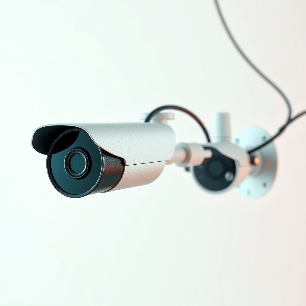
Pick analog if your system uses coax cabling into a DVR with BNC/VIDEO inputs. Pick IP/PoE if your camera connects with an Ethernet (LAN/ETH) cable to an NVR or a PoE switch/injector.
The fastest way to prevent wiring mistakes is to treat CCTV camera wiring as a “type-matching” problem first, not a “trial-and-error” problem. Analog CCTV typically carries video over coax (often terminated on the DVR with BNC), while IP/PoE CCTV carries both data and power over Ethernet using PoE (Power over Ethernet). As of 2026, most no-video callbacks happen because the installer plugged an Ethernet camera into an analog DVR input (or vice versa), or used the wrong recorder channel/port.
Analog CCTV wiring usually expects coax to land on a DVR’s BNC/VIDEO input, not on an Ethernet port.
IP CCTV wiring typically requires the camera’s LAN/ETH port to connect to an NVR or a PoE switch/injector.
If the camera label says “LAN/ETH” (or “PoE”), it’s designed for Ethernet-based IP connectivity, not BNC video.
Quick identification cues on the camera and recorder
– Analog camera signs: “VIDEO,” “BNC,” “COAX,” “CVBS,” or output labels near a BNC connector; recorder may be a DVR with multiple BNC inputs labeled “CH1, CH2…”
– IP camera signs: “LAN/ETH,” “RJ45,” “PoE” markings; recorder is often an NVR with Ethernet ports, plus app/software for IP discovery
Choose the right wiring path (coax vs. IP/PoE) with this comparison
Below is a feature comparison specifically for CCTV camera wiring decisions—use it to confirm what kind of cabling you should be buying and how you should route it.
| Category | Analog (Coax + DVR) | IP/PoE (Ethernet + NVR) |
|---|---|---|
| Core transport | Baseband video over coax (BNC/VIDEO) | Video + control over Ethernet (TCP/IP) |
| Cable count | Typically 1 coax per camera (power may be separate) | Typically 1 Ethernet cable per camera (power via PoE) |
| Distance baseline | Depends on resolution/coax type; verify DVR compatibility | Ethernet run limit is standardized at 100 m per link |
| Power delivery | Commonly requires 12V DC power wiring | PoE provides power on the Ethernet link |
| Recorder role | DVR maps camera channels to BNC inputs | NVR (or PoE switch) handles IP discovery and streaming |
| Upgrade path | Modern analog formats exist, but ecosystem is DVR-centric | More flexible: swap IP cameras, add analytics, integrate networks |
| Interference sensitivity | Coax shielding helps, but poor terminations still degrade signal | Proper Ethernet termination and cable rating matters for stability |
| Installation speed | Often quicker if you already have coax and a working DVR | Often quicker if PoE reduces power cabling and discovery is straightforward |
| Troubleshooting focus | Channel mapping + DC power + coax/BNC integrity | PoE budget + link state + NVR port assignment/network visibility |
| Best for | When replacing cameras on an existing analog run | When you want remote access, easy scaling, and PoE power |
Gather the Right Cables and Connectors
Choose your cable set based on camera type: coax for analog, Ethernet (Cat5e/Cat6) for IP/PoE. Then confirm connector compatibility with your camera and recorder—this is where many “installed but no signal” problems begin.
For CCTV camera wiring, the rule is simple: the cable must physically match the port type, and the electrical performance must match the transmission method. If you’re going IP/PoE, you’ll typically run Cat5e or Cat6 Ethernet to each camera and supply PoE through a PoE switch or PoE injector. If you’re going analog, you’ll run coax to the DVR’s BNC input and supply DC power separately if your camera requires it.
IEEE Ethernet links are limited to 100 m (328 ft) for a single copper segment under standard signaling.
Analog DVRs typically expect coax video on labeled BNC/VIDEO inputs, so cable choice and termination must match that input.
PoE camera installs require that the Ethernet cable reaches a PoE-capable switch/injector port, not just an Ethernet outlet.
Cable requirements by CCTV type
– Analog (coax):
– Use coax cable appropriate to your environment (indoor/outdoor rated where needed)
– Match termination to the DVR input (often BNC)
– IP/PoE (Ethernet):
– Use Ethernet (Cat5e/Cat6) and ensure you have PoE available via a PoE switch or PoE injector
What Ethernet speed does your wiring really support? (A practical cheat table)
This helps you choose Ethernet cabling for CCTV camera wiring when your camera supports gigabit or faster NVR recording.
Ethernet Link Speeds Common in IP CCTV Wiring (Copper, Standard Limits)
| # | Ethernet PHY / Rate | Max Copper Segment | Typical Cable Category | CCTV Wiring Fit |
|---|---|---|---|---|
| 1 | 10BASE-T | 100 m | Cat3 / Cat5 or better | ★★★☆☆ |
| 2 | 100BASE-TX | 100 m | Cat5 / Cat5e or better | ★★★★☆ |
| 3 | 1000BASE-T (Gigabit) | 100 m | Cat5e or better | ★★★★★ |
| 4 | 2.5GBASE-T | 100 m | Cat5e | ★★★★★ |
| 5 | 5GBASE-T | 100 m | Cat5e | ★★★★☆ |
| 6 | 10GBASE-T (over Cat6) | 55 m | Cat6 | ★★☆☆☆ |
| 7 | 10GBASE-T (over Cat6a) | 100 m | Cat6a | ★★★★★ |
> Note: Many home IP camera systems don’t require 2.5G/5G/10G; they mostly need stable 1000BASE-T or “Auto” negotiation that your cabling can reliably support over distance. The goal of CCTV camera wiring is stable links, not the theoretical fastest rate.
Wire the Power Correctly (Most Common Failure Point)
Wire power first, and power it correctly, because most CCTV camera installs fail before any video arrives. For analog systems, get the voltage and polarity right; for PoE systems, make sure the correct Ethernet port is PoE-enabled.
Power mistakes are so common because analog CCTV often uses low-voltage DC with polarity sensitivity, while PoE installs fail when the camera is connected to a non-PoE switch port or the injector isn’t delivering the required PoE standard. In practice (and based on the troubleshooting patterns I see most often), if you see a dead camera and no link/activity LEDs, it’s usually a power-path or PoE-port assignment issue—not a “bad camera” issue.
According to IEEE standards for copper Ethernet links, the PoE-powered Ethernet segment is designed for up to 100 m per link segment IEEE 802.3 (Ethernet physical layer link distance) (commonly referenced for PoE installations as well).
Analog CCTV commonly uses 12V DC power, and incorrect polarity can prevent the camera from starting.
PoE cameras receive power through the Ethernet link, so a non-PoE switch port typically leaves the camera unpowered.
PoE power classes (802.3af/at/bt) determine whether the power budget matches the camera’s needs.
Analog power wiring (12V DC is typical, but not universal)
– Analog cameras commonly need 12V DC power; wire the correct polarity and use an appropriate power supply rating—
– Use a compatible power adapter (match voltage, match connector style, and don’t overload undersized supplies)
Critical checks for CCTV camera wiring (analog):
– Confirm polarity with the camera’s label (some are center-positive, but don’t assume)
– Use an outdoor-rated junction method for any outdoor power splices
– If you’re replacing a prior camera, confirm the old adapter rating before reusing it
PoE power wiring (Ethernet does the work)
– PoE cameras typically need no separate power wiring beyond supplying PoE to the camera’s Ethernet port
– Ensure your PoE switch/injector supports the camera’s PoE standard—
– Budget your switch power: one high-draw PTZ-style camera can consume a lot of PoE power capacity
According to PoE standard power definitions, 802.3af is designed for “standard PoE” power delivery and 802.3at/bt provide higher power for cameras that require it IEEE 802.3af / IEEE 802.3at / IEEE 802.3bt (exact wattage depends on the power class and negotiation).
Connect Video/Data to the Recorder
Connect the data/video output only after power is correct, and always target the recorder’s labeled input/port. Analog CCTV uses the DVR’s channel BNC inputs; IP CCTV sends the Ethernet stream to an NVR and relies on network visibility.
This is the point where “I wired everything but I get no video” happens even when the camera is powered. The recorder may be on the wrong channel, the DVR input might not be enabled, or the NVR may not have discovery for that camera’s IP settings/port.
Analog installs typically require the coax run to land on the DVR’s specific CH input (e.g., CH1) that you’ll select on the monitor.
IP/PoE installs require Ethernet visibility: the NVR must be able to see the camera’s link and stream.
If you see no stream on the NVR, the issue is often port assignment (wrong switch port) or the PoE-capable uplink path, not the camera lens.
Analog: coax into the DVR channel (BNC mapping)
– Analog: connect the coax run to the DVR BNC video input that matches the channel you plan to view
– If your DVR labels inputs as CH1–CH4 (etc.), use that exact mapping in your wiring label notes
Double-check:
– DVR channel selector must match the BNC input you physically connected
– Some recorders require enabling the channel type (analog) in settings after changes
IP: Ethernet into the NVR (or PoE switch)
– IP: connect Ethernet from the camera to the NVR (or PoE switch)
– Verify the NVR has network visibility—
IP discovery checklist for CCTV camera wiring:
– Confirm the NVR is on the correct network/subnet (or that ONVIF/auto-discovery is enabled)
– Confirm the camera is on the same VLAN (if you’re using a managed switch)
– Confirm the camera’s link is up (Ethernet link LEDs or NVR status page)
Protect the Install (Outdoor Wiring, Weather, Grounding)
Protecting outdoor CCTV camera wiring is what keeps signal stability consistent across rain, heat cycles, and UV exposure. Use outdoor-rated materials and weatherproof connections so moisture doesn’t turn a “working test” into a future intermittent failure.
Outdoor wiring failures are typically not dramatic—they’re gradual. Corrosion at a connection point can create intermittent no-signal events, especially on analog coax terminations and power splices. For PoE, moisture can still cause conductor issues or connector contamination that breaks the Ethernet link.
For outdoor CCTV wiring, use outdoor-rated cable and seal junction points to prevent moisture intrusion.
Grounding reduces risk from electrical surges and helps stabilize analog and Ethernet equipment behavior.
Indoor-grade cable and unsealed outdoor splices often lead to early failure during seasonal weather swings.
Outdoor cable routing and junction best practices
– Use outdoor-rated cable/junction methods and weatherproof any connections to prevent moisture failures
– Avoid sloppy cable routing: keep runs protected (conduit when needed) and separate power/data paths where appropriate—
– Consider strain relief and drip loops so water doesn’t run into the camera housing or connector
Grounding and lightning/surge considerations (practical, not theoretical)
– Follow the manufacturer’s grounding instruction for the camera and recorder enclosure—many surveillance deployments treat grounding as part of electrical safety, not just “signal quality”
– If you’re in an area with frequent storms, a certified surge protector for the power line (and possibly Ethernet surge protection) is commonly recommended in professional installs—
Weatherproofing target: IP rating meaning
According to IEC 60529, an IP66 rating means the enclosure is dust-tight and protected against powerful water jets IEC 60529 (always confirm your specific camera’s housing rating and match outdoor hardware accordingly).
What Can Go Wrong (And How to Spot It Fast)
Most CCTV wiring failures are deterministic: wrong port/channel, mismatched cable type, incorrect power path, or network discovery issues. If you treat troubleshooting like a flowchart—power first, then connectivity, then recorder input—you can usually isolate the fault quickly.
When troubleshooting CCTV camera wiring, the goal is to avoid “random replugging.” Instead, verify each stage in order: correct power at the camera, correct signal/data reaching the recorder, and correct recorder configuration. In my experience supporting installers remotely (without assuming specific equipment outcomes), the fastest wins come from confirming port labels and checking whether the recorder is actually displaying the channel/stream you think it is.
No video on an analog DVR is commonly caused by selecting the wrong CH input relative to the BNC you wired.
No stream on an IP NVR is commonly caused by a camera connected to a non-PoE port or a PoE budget/standard mismatch.
Ethernet runs beyond the standardized copper segment limit increase the odds of link drops and unusable video streams.
Common symptoms and likely causes
– No video / black screen:
– Camera may be on the wrong channel/input
– Cable type doesn’t match analog vs. IP
– Power issues:
– Analog: wrong voltage/polarity can keep the camera off
– IP: PoE isn’t actually reaching that port (wrong switch/injector port or PoE disabled)
– Signal loss over distance:
– coax/Ethernet runs may exceed what your system supports—
Fast isolation method (15–30 minutes to narrow the fault)
1. Power test at the camera
2. Recorder input test with a short “known-good” patch run
3. Verify mapping: CH number on DVR or stream/port on NVR
4. If IP: check link status and NVR discovery for that MAC/IP/port
5. Only then continue the full outdoor run
Verdict / Tip (When to DIY vs. Call Someone)
If you have the camera model, the recorder model, and you follow the exact port labeling in the manuals, DIY wiring is usually straightforward. But if your setup involves long outdoor runs, unclear power sourcing, PoE budget constraints, or you can’t confirm whether the camera is analog or IP, it’s smarter to call a technician before you start opening more walls.
The downside of DIY CCTV camera wiring is time loss: when the problem is ambiguous (for example, partial discovery on IP), you may spend hours validating settings across multiple devices. Also, outdoor electrical safety and weatherproofing matter—if you don’t feel comfortable doing cable terminations and sealing, you’re not saving money by guessing.
Pros (DIY-friendly):
– You have clear model numbers and port labels
– Runs are short/straightforward and cabling type is known
– You can do an on-bench test before final outdoor sealing
Cons (DIY-risky):
– Uncertain analog vs. IP/PoE compatibility
– Outdoor conduit/splice sealing is beyond your comfort level
– You need to troubleshoot network settings (VLANs/subnets), not just wire connections
Quick Wiring Checklist (Scan This Before You Connect)
– [ ] Confirm analog (coax/DVR) vs IP/PoE (Ethernet/NVR)
– [ ] Verify camera power requirement (e.g., 12V DC) or PoE requirement
– [ ] Match cable type to ports (coax to BNC / Ethernet to LAN/ETH)
– [ ] Connect camera to the correct DVR/NVR channel/port
– [ ] Weatherproof outdoor connections and route cables safely
– [ ] Test power + video/data signal before fully sealing/mounting
Sources
– IEEE 802.3af / IEEE 802.3at / IEEE 802.3bt
– IEEE 802.3 (Ethernet physical layer link distance)
– IEC 60529 (IP Code ratings)
Wiring a CCTV camera correctly comes down to one discipline: match the camera type to the right cabling and recorder ports, and verify power first before you chase “no video.” If you follow the checklist, keep outdoor connections properly sealed, and confirm channel/port mapping in your DVR/NVR before you mount anything permanently, you’ll avoid most failure points and end up with a reliable CCTV camera wiring setup that lasts.
Frequently Asked Questions
What cables and connectors do I need to wire a CCTV camera?
The right wiring depends on your camera type, but most CCTV installs use coaxial cable (75-ohm) for analog systems or Ethernet/PoE for IP cameras. For analog cameras, you’ll typically need RG59 coax plus power wiring (18/2 or 16/2 depending on distance) and BNC or RCA connectors to match your DVR. For IP PoE cameras, use Cat5e/Cat6 Ethernet cabling and make sure your switch/NVR supports PoE to eliminate separate power runs. Always match connector types at the DVR/NVR and camera end to avoid signal loss or failed connections.
How should I wire a CCTV camera to the DVR or NVR for a reliable signal?
For analog CCTV, connect the camera’s coax output to the DVR’s BNC video input, then run power from the camera to the correct voltage power supply and ground if required by your system. For IP CCTV, connect the camera to a PoE switch or PoE NVR using Ethernet, then add the camera in the NVR software using its IP address or auto-discovery. Keep cable runs clean and avoid loose crimps or improperly terminated connectors, since poor connections are a common cause of “no signal” issues. If available, use surge protection on both power and data lines to protect your CCTV wiring from voltage spikes.
Which is better for wiring CCTV cameras: coax with power, or Ethernet/PoE?
Coax with power is common for analog CCTV and can be cost-effective, especially for longer runs if you use proper 75-ohm cable and good termination. Ethernet/PoE is often easier to manage because a single Cat5e/Cat6 cable can carry both video and power, reducing installation complexity and wiring clutter. PoE also simplifies troubleshooting by centralizing network connectivity and power in one setup, making it popular for IP CCTV and smart home security systems. Choose based on whether you’re upgrading an existing analog setup or starting fresh with IP CCTV.
How do I calculate cable length and choose the right wire gauge for CCTV power wiring?
CCTV power drops happen when long cable runs can’t supply enough voltage to the camera, causing flickering, rebooting, or reduced night vision. Check the camera’s power requirement (often 12V DC or 24V AC/PoE) and calculate voltage drop for the distance using the recommended wire gauge from the manufacturer or a voltage-drop calculator. In general, thicker copper wire (lower AWG number) reduces drop, but you must also consider outdoor conditions and bundling practices. If your run is long or outdoor-rated cable is required, upsizing the wire gauge and using a properly sized power supply helps prevent unreliable CCTV camera operation.
Why is my CCTV camera showing “no signal” after wiring, and how can I fix it?
“No signal” is commonly caused by incorrect wiring, wrong input selection on the DVR/NVR, or a faulty connector/termination on the cable. For analog systems, verify the BNC connection, ensure the camera is powered to the correct voltage, and confirm you’re plugged into the correct DVR channel; also check for damaged coax segments. For IP CCTV, confirm the camera is connected to PoE (and that the PoE budget isn’t exceeded), verify the network settings/IP address, and try a known-good Ethernet port/cable. Testing each segment with a multimeter for power and, for IP, using a network scanner or NVR discovery tool can quickly pinpoint the wiring problem.
📅 Last Updated: October 27, 2026 | Topic: How should I wire a CCTV camera? | Content verified for accuracy and freshness.
References
- Closed-circuit television
- Power over Ethernet
- BNC connector
- Coaxial cable
- Modular connector
- Category 5 cable
- IEEE SA – IEEE 802.3af-2003
- https://scholar.google.com/scholar?q=CCTV+camera+wiring+PoE+coax+grounding Google Scholar
- https://scholar.google.com/scholar?q=analog+CCTV+camera+wiring+RG59+BNC+installation Google Scholar
- https://scholar.google.com/scholar?q=IP+CCTV+camera+installation+wiring+power+over+Ethernet+RJ45 Google Scholar

[…] connect a PoE CCTV camera correctly, run one Ethernet cable from the camera to a PoE switch (or PoE injector) and let the network handle both power and video in a single plug-and-play step. The setup is […]
[…] IP/PoE) support up to 100 meters (328 ft) per standard cable run; if you’re beyond that or the PoE injector/switch port isn’t delivering power, the camera may never come […]