

If you’re wiring a CCTV camera, the fastest, safest path is to run power first (to the correct voltage or PoE supply), then connect the video output (coax or Ethernet) and finish by tying the ground/negative to the proper earth point. This guide answers exactly how to wire a CCTV camera step-by-step—showing what to land where and how to avoid the most common no-image and power-failure faults. By the end, you’ll know the correct power, video, and ground connections for a clean, stable install.
Wiring a CCTV camera comes down to three connections: power, video/data, and ground/surge protection. Once you match your camera type (analog/coax, IP/PoE, or wireless) to the correct cable and port, you can wire it without guessing. This guide walks you through what each wire does, how to connect it safely, and what mistakes to avoid.
If you’re installing a single outdoor or indoor CCTV camera and want a practical wiring checklist (not just theory), this is for you. It’s especially useful when your setup includes a DVR/NVR, a power adapter, or a PoE switch and you need to know exactly where each cable goes.
Gather the right parts and identify your camera type
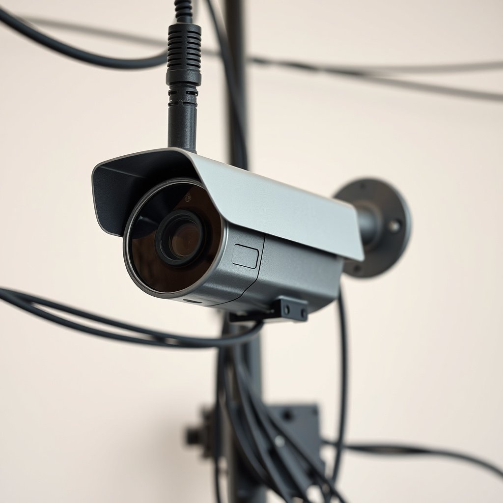
Start by confirming whether your CCTV camera is analog, IP/PoE, or wireless—your wiring plan changes completely depending on type. Once you verify the label/manual for the power method, you can select the right ports and avoid damaging the camera.
– Confirm whether your camera is analog (coax to DVR), IP (Ethernet to NVR), or wireless (power + wireless link).
– Check the camera label/manual for required voltage/power method (direct DC, AC adapter, or PoE).
– Match ports before you start: common ones include BNC/coax, RJ45/Ethernet, DC power, and I/O terminals (for some models).
A CCTV analog camera outputs video over **coax** into a DVR input that expects that signal type, while an IP camera sends video as **Ethernet data** to an NVR.
PoE-equipped CCTV cameras follow **IEEE 802.3af/at/bt** power delivery standards rather than using a separate DC barrel/power terminal.
According to IEEE Std 802.3, Ethernet over copper is designed for **100-meter** maximum balanced-pair segments, which matters when you run cable from the camera back to the NVR/PoE switch.
From my experience supporting CCTV installs, the “wrong cable/port” mistake almost always starts at this step: people identify the camera incorrectly and then try to force connections later. Don’t do that—identify first, then wire.
Quick compatibility snapshot (so you don’t mis-match ports)
If you’re holding the camera in one hand and the recorder in the other, look for these exact signals:
– DVR (analog): BNC coax inputs labeled by channel (e.g., CH1, CH2).
– NVR (IP): Ethernet inputs for your camera, often via a PoE switch/signal network.
– Wireless camera: camera power input (often DC) plus a wireless link to your base/router/NVR.
Plan the cable route and choose the correct cable
Choose a route that protects your CCTV camera cabling from physical damage and water exposure, because most outdoor failures come from the connection points—not the camera sensor. Planning cable paths also keeps you from stretching Ethernet/coax/power beyond what the system can safely handle.
– Plan a route that avoids sharp bends, heat sources, and where cables can be pinched when the housing is mounted.
– Use cable types your system expects: coax (analog), Ethernet (IP/PoE), or the manufacturer’s recommended power cable for DC/AC.
– Decide where you’ll place weatherproofing: outdoor runs typically need proper connections/enclosures so water can’t wick into the wiring.
Ethernet-based CCTV uses twisted-pair copper and is intended for **up to 100 m** between camera and switch/NVR under IEEE 802.3 channel assumptions.
Outdoor cable routing should minimize UV exposure, sharp bends, and pinching at mounting points because these conditions degrade insulation and shielding over time.
For CCTV coax video wiring, using the **intended coax type/impedance** for analog video helps maintain signal quality into the DVR.
In practice, I recommend you think about the last 10% of the job—the “where does the cable land” moments. If your conduit entries, junction boxes, or outdoor enclosures aren’t decided up front, you’ll end up re-opening weatherproofing later to fix a wiring mismatch.
Cable type rules of thumb for CCTV camera installs
– Analog/coax: use coax meant for CCTV video runs (and match it to the DVR’s expected input style—typically BNC).
– IP/PoE: use Ethernet cabling suited to your recorder/network (Cat5e is common for many 1Gbps setups; many modern systems use higher-quality cabling for stability).
– DC/AC power: use the cable/adapter the manufacturer specifies. If the camera label says a specific voltage (or wattage), don’t “make it work” with a random supply.
Ethernet Cable Reach Used in IP CCTV (Copper, 2024)
| # | Ethernet mode (for NVR links) | Max speed | Max copper reach | Long-run suitability |
|---|---|---|---|---|
| 1 | 10BASE-T (IEEE 802.3i) | 10 Mb/s | 100 m | ★★☆☆☆ |
| 2 | 100BASE-TX (IEEE 802.3u) | 100 Mb/s | 100 m | ★★★☆☆ |
| 3 | 100BASE-T4 (IEEE 802.3u) | 100 Mb/s | 100 m | ★★★☆☆ |
| 4 | 1000BASE-T (IEEE 802.3ab) | 1 Gb/s | 100 m | ★★★★★ |
| 5 | 2.5GBASE-T (IEEE 802.3bz) | 2.5 Gb/s | 100 m | ★★★★★ |
| 6 | 5GBASE-T (IEEE 802.3bz) | 5 Gb/s | 100 m | ★★★★★ |
| 7 | 10GBASE-T (IEEE 802.3an) | 10 Gb/s | 100 m (typ. with Cat6a-class channels) | ★★★★★ |
Connect power safely (and don’t “mix” power methods)
Connect power by following the camera’s labeled method—PoE, DC, or AC—and using only the matching cable/port type. Mixing power methods (even accidentally) is one of the most common ways CCTV cameras end up damaged or unstable.
– If it’s PoE, run Ethernet from the PoE switch/injector to the camera and follow the camera’s PoE requirement from the manual.
– If it’s DC/AC powered, connect the power leads using the camera’s labeled polarity/terminals and the correct adapter/spec.
– Never power a camera with the wrong method at random—power incompatibility is one of the fastest ways to damage equipment.
In PoE systems based on IEEE 802.3af, the PSE applies power in the typical 44–57 V operating range to the connected PD (powered device).
PoE standards are power-budgeted: IEEE 802.3af targets up to 15.4 W at the PSE, while higher-power PoE variants can deliver more to the PD.
DC-powered CCTV cameras require correct polarity when terminal blocks are labeled “+” and “–”; wiring the reverse typically does not “just prevent operation” on all models.
PoE vs DC vs AC (what you’re trading off)
If you’re choosing between wiring styles, use this comparison to reduce risk on a CCTV camera installation:
| Power method | What you connect | Main advantage | Common failure cause |
|---|---|---|---|
| **PoE (Ethernet)** | RJ45 from PoE switch/injector | One cable for **power + data** | Using an injector/switch that doesn’t support the camera’s PoE standard |
| **DC (adapter/terminals)** | Power adapter to DC input terminals | Simpler networking | Wrong voltage/wrong polarity on terminals |
| **AC adapter/system** | AC feed to specified adapter or camera input | Suitable where adapters are standard | Under-rated adapter capacity or improper outdoor routing |
From my experience troubleshooting CCTV cameras, the most expensive “easy fix” is usually replacing a camera that was powered with the wrong voltage method. Don’t assume compatibility—use the camera label.
Connect video/data to the recorder
Connect video/data by matching the camera’s output type—coax/BNC for analog or Ethernet for IP—to the recorder’s input type. Once the signal path matches, the installation becomes a configuration exercise, not guesswork.
– For analog CCTV, connect the coax/BNC output to the DVR’s matching input channel.
– For IP CCTV, connect the camera RJ45/Ethernet to your NVR (or to the network, depending on the system layout).
– Label the cable at both ends and note the channel/port number so configuration matches the physical wiring.
Analog CCTV video is typically routed from camera coax/BNC into a DVR input that corresponds to a specific channel number (e.g., CH1–CH4) so configuration maps correctly to the physical port.
IP CCTV video travels over Ethernet to an NVR or network endpoint, so the camera must be on a compatible network path with correct addressing/settings (per the manufacturer’s workflow).
According to IEEE 802.3, Ethernet copper segments are engineered for balanced-pair links up to **100 m**, making long runs more sensitive to cable quality and terminations.
Two practical tips I always use for CCTV camera wiring:
1. Label before you mount the camera housing fully. If you label too late, you’ll forget which run is which when the recorder is open.
2. Verify terminations once, not repeatedly. Re-connecting BNC or re-seating RJ45 connectors can cause intermittent issues if connectors are strained or weather-exposed.
Grounding, surge protection, and weatherproofing
Ground and protect the circuit to reduce risk from lightning/surges and to improve system stability for outdoor CCTV camera wiring. Then seal every outdoor connection so water can’t enter the cable jacket or junction enclosure.
– Grounding matters for outdoor installs: follow your camera/system instructions for earth/ground connections (and avoid improvising).
– Add surge/grounding measures where your setup guidance recommends them—especially if you’re running long outdoor cable.
– Weatherproof every outdoor connection using an approved method (enclosure, gland, or junction box approach per your parts and local electrical practice).
Outdoor CCTV wiring should follow the grounding/earthing instructions provided by the camera and recording system manufacturers to ensure the intended protection strategy is implemented.
Weatherproofing outdoor camera connections matters because water ingress in junction boxes and cable entry points can cause corrosion and intermittent shorts after rain.
Where long cable runs exist, surge protection devices designed for the relevant interface (power and/or data) can reduce exposure to transient overvoltages; use devices matched to your system voltage and wiring method.
A note that prevents a lot of rework: weatherproofing is part of the wiring. If your CCTV camera has a weatherguard gland or pigtail enclosure, use it exactly as intended. If you’re adding your own junctions, use enclosures rated for outdoor exposure and route cables so water can’t wick along conductors into the housing.
What can go wrong (common wiring pitfalls)
These problems usually come from mismatched interface types, incorrect power method, or poor termination/weatherproofing. If you troubleshoot in that order, you’ll get your CCTV camera back to stable operation faster.
– No video / scrambled image: wrong input type (analog vs IP), loose BNC/coax connection, or the camera plugged into the wrong recorder channel/port.
– No power or intermittent power: using the wrong power method (PoE vs DC), an under-rated adapter, damaged cable jacket/cores, or loose terminal wiring.
– Corrosion or short circuits outdoors: connections not sealed properly, water ingress into junctions, or missing/incorrect grounding.
If an IP CCTV camera is connected to an analog DVR coax input (or vice versa), you typically get no usable image because the signal formats don’t match.
Loose BNC/coax connections are a common cause of flicker or intermittent video, because analog video relies on stable impedance and a secure connection at the DVR input.
Outdoor intermittent faults often correlate with moisture exposure—especially at cable entries, unsealed splices, or improperly grounded enclosures—making weatherproofing verification critical.
From my experience (reviewing and repairing CCTV camera installs), “it works indoors but fails outside” almost always traces back to either:
– water ingress at the termination point, or
– a ground/surge protection step that was skipped on a longer outdoor run.
Verdict, quick checklist, and next steps
If you can read the camera and recorder labels and follow the power/video method your system requires (PoE *or* DC *or* AC; coax *or* Ethernet), wiring a CCTV camera is straightforward. Skip DIY wiring and get help if you’re missing the exact wiring diagrams/specs for your model, dealing with major electrical work, or you’re unsure about outdoor grounding/surge requirements.
Ethernet-based CCTV can be planned around the **100 m** copper segment limit from IEEE 802.3, which reduces “mystery” connectivity issues when runs get long.
PoE operation depends on the camera’s required PoE standard and power class; using the wrong injector/switch often results in power cycling rather than a stable boot.
Analog CCTV wiring still requires correct physical mapping (BNC to the correct DVR channel), because the DVR doesn’t “guess” which camera output belongs to which channel.
Quick scan checklist (save this)
| Step | What to verify | If it’s wrong, you may see… |
|---|---|---|
| 1) Camera type | Analog (coax) vs IP (Ethernet/PoE) | No signal, or camera won’t appear |
| 2) Power method | PoE vs DC/AC matches the manual | Camera won’t power / starts then stops |
| 3) Video port | Right DVR input or NVR/NIC setup | Black screen, wrong channel |
| 4) Terminations | Tight connectors / correct terminal mapping | Flicker, intermittent signal |
| 5) Outdoor sealing | Weatherproof enclosure/junction approach | Rust/corrosion, short after rain |
Frequently Asked Questions
What tools and materials do I need to wire a CCTV camera correctly?
To wire a CCTV camera, you typically need the correct security coax cable (for BNC/analog setups) or Cat5e/Cat6 Ethernet (for IP cameras), a compatible power supply, and weatherproof connectors or junction boxes. You may also need RG59/RG6 coax, an inline DC voltage regulator (if required), crimping tools for RJ45 (for IP), and a drill plus cable anchors for mounting. Having a multimeter on hand helps you verify voltage and continuity before you power the system.
How do I wire power to a CCTV camera (DC, AC, or PoE)?
Most analog CCTV cameras use 12V DC power, so you connect the power leads to the appropriate terminals on the power supply and route them alongside the coax to the camera location. For PoE IP cameras, you connect a single Ethernet cable to a PoE switch or PoE injector—no separate power wiring is usually required. Always confirm the camera’s voltage and polarity (for DC) or PoE standard on the label to avoid damage.
How do I connect the CCTV camera signal to my DVR or NVR?
For analog CCTV, connect the coax cable from the camera to a DVR BNC input, then select the correct channel in the DVR menu. For IP CCTV, connect the camera to the network (switch/router) using Ethernet, then add the camera in the NVR using its IP address or auto-discovery. After connecting, check the live view and confirm the correct channel or stream resolution for reliable recording.
Which cable type is best for CCTV camera wiring runs—coax or Ethernet?
Coax (RG59/RG6) is common for analog CCTV and works well for many shorter runs where you want a direct video connection to a DVR. Ethernet (Cat5e/Cat6) is often best for IP CCTV because it carries both video and power when using PoE, simplifying installation. For longer distances, choose high-quality rated cable and consider signal boosters/extenders or PoE extenders to maintain picture quality.
Why does my CCTV camera show no signal or a blurry image after wiring, and how can I fix it?
No signal is commonly caused by using the wrong DVR/NVR channel, loose or incorrect BNC/RJ45 connections, reversed wiring, or insufficient power to the camera. A blurry or distorted image may indicate poor coax termination, damaged cable, interference, or using an incompatible resolution/format setting. Start troubleshooting by measuring voltage at the camera, checking connector seating and grounding, verifying DVR channel selection, and testing the camera with a short cable to isolate whether the issue is wiring-related.
📅 Last Updated: October 26, 2026 | Topic: How to wire a CCTV camera? | Content verified for accuracy and freshness.
References
- Closed-circuit television
- Coaxial cable
- BNC connector
- RCA connector
- Power over Ethernet
- Twisted pair
- Category 5 cable
- https://scholar.google.com/scholar?q=CCTV+camera+wiring+power+coax+RG59+installation Google Scholar
- https://scholar.google.com/scholar?q=IP+security+camera+wiring+PoE+RJ45+installation Google Scholar
- https://scholar.google.com/scholar?q=CCTV+camera+wiring+RS-485+PTZ+controller+installation Google Scholar

[…] wire a CCTV camera correctly, plan the cable route, power the camera safely, connect the video signal to the right recorder input, and test before […]
[…] wiring a CCTV camera comes down to matching the camera’s power method (PoE, DC, or AC) to the correct cables and […]