
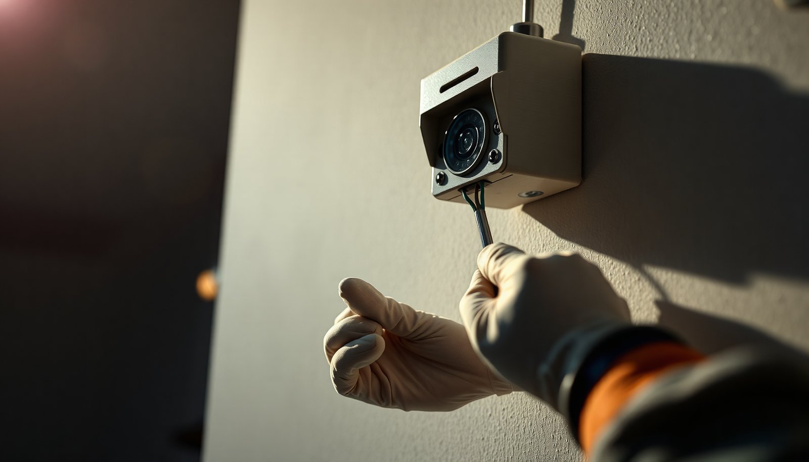

You’re standing at the front door with a CCTV camera in one hand and a bundle of power and video cables in the other, trying to figure out which wire goes where without risking a short or a dead signal. You can wire a compatible system safely and neatly in a couple of focused hours, as long as you have the right tools, match the camera’s voltage and connector type, and follow the wiring color code and polarity correctly. Once you do, you will avoid the most common mistakes that cause flicker, loss of recording, or overheating.
Safely wiring a CCTV camera comes down to matching the camera’s power method (PoE, DC, or AC) to the correct cables and wiring order—and testing before you seal anything. In this guide, you’ll learn how to identify your camera type, wire power safely (including grounding), make the right video/network connections, and do a quick verification so you don’t end up with no image or a fried camera.
This is for homeowners, renters, and small business owners installing a CCTV camera at a residence or office—especially if you’re unsure whether you should run mains voltage, use PoE, or connect the right kind of coax/Ethernet.
Safety & preparation
If you want “no mistakes,” the fastest path is preparation: read labels, confirm the wiring diagram, and control power before you touch anything. Once you do that, the rest of the CCTV camera wiring process becomes a straightforward sequence of matching the right power and signal connections.
– Read the camera and power-source labels first (output voltage/current and connector types), then follow the manufacturer’s wiring diagram.
Before you pick up a screwdriver for CCTV camera wiring, confirm the exact output your camera expects (for example, 12V DC, 24V DC, or a specific AC transformer spec). Labels on IP cameras and adapters often include the input voltage range and the polarity details for DC leads (e.g., “+ on center conductor” for coax-style power plugs). If the manual shows a terminal block (like + / – / GND), treat that as authoritative—don’t infer it from color alone.
– Turn off power at the source before touching any wires; if the job involves mains/line voltage, use a qualified electrician.
For CCTV camera wiring, “off” must mean isolated: switch off the relevant breaker or disconnect, and verify voltage absence using a proper tester. If you’re working with mains/line voltage (typically AC-power setups), local electrical codes and safety risks increase significantly—this is where a licensed electrician is the right call.
– Plan where cables will route (drip loops, protected entry points) so water doesn’t run into junctions or connectors.
Weather failure is a common CCTV camera wiring problem. Plan for cable paths that create drip loops (a downward loop so water drips off before it reaches connectors), and ensure any exterior cable entry uses an appropriate gland, conduit, or outdoor-rated junction box. A “working today” installation that lacks strain relief and weather protection often fails months later.
Identify your camera type and power method
The safest CCTV camera wiring starts by identifying whether you have PoE, DC, or AC, because each method uses different cabling and terminal behavior. Once the power method is correct, you can confidently map the signal connection (coax for analog or Ethernet for IP) to the right recorder.
– Determine whether your camera is PoE (Power over Ethernet), DC-powered (commonly via a labeled adapter), or AC-powered (often via a specific transformer/adapter).
Look for “PoE” on the camera label, or a model number that explicitly states PoE compatibility. For DC-powered CCTV camera wiring, you’ll typically see a DC voltage requirement (like 12V or 24V) plus polarity guidance. For AC-powered systems, the package usually references a transformer output (often 24VAC), not a generic wall wart.
– Identify the signal type: coax (analog) or IP/Ethernet (digital)—this dictates whether you’ll terminate BNC/coax connections or run Ethernet to an NVR/switch.
This matters because analog CCTV camera wiring uses coaxial video (usually terminated with BNC or similar fittings), while IP CCTV camera wiring uses Ethernet (RJ45) and then connects to an NVR (Network Video Recorder) or an IP switch.
– Confirm required hardware: DVR vs NVR, PoE switch/injector (if PoE), and the correct cable (coax type or Ethernet category) listed in the manual.
A PoE camera still needs a PoE source—either a PoE switch or a PoE injector. Analog cameras need the matching DVR input, while IP cameras need the right recorder/network interface.
- PoE vs DC vs AC for CCTV camera wiring
-
PoE (Power over Ethernet)
Pros: single Ethernet run handles data + power; reduces polarity/voltage mismatch risk when using the correct PoE injector/switch and outdoor-rated Ethernet cable.
Cons: still requires correct PoE standard/support; long runs must stay within Ethernet distance limits and use suitable cable ratings. -
DC-powered
Pros: simple when polarity is clearly labeled; compatible with many adapters and setups.
Cons: polarity mistakes can damage CCTV camera wiring; voltage drop on longer runs can cause resets or IR issues. -
AC-powered
Pros: works with specific transformers designed for camera systems.
Cons: involves higher electrical risk; wiring order/grounding requirements matter more, and DIY mains wiring may violate local code.
PoE power levels you must match to PoE CCTV camera wiring
| # | PoE standard / mode | Power on RJ45 pins | Max power at PD (camera side) | What it’s commonly used for |
|---|---|---|---|---|
| 1 | IEEE 802.3af (Type 1) — Mode A | Pins 4–5 & 7–8 | 12.95W | Basic indoor/outdoor PoE cameras |
| 2 | IEEE 802.3af (Type 1) — Mode B | Pins 1–2 & 3–6 | 12.95W | Budget PoE CCTV cameras |
| 3 | IEEE 802.3at (Type 2) — Mode A | Pins 4–5 & 7–8 | 25.5W | Cameras with heaters/strong IR |
| 4 | IEEE 802.3at (Type 2) — Mode B | Pins 1–2 & 3–6 | 25.5W | PoE + cameras for moderate workloads |
| 5 | IEEE 802.3bt (Type 3) — Mode A | Uses both pair groups | 51W | Higher-power PTZ/IR-heavy cameras |
| 6 | IEEE 802.3bt (Type 3) — Mode B | Uses both pair groups | 51W | Industrial-grade PoE camera installs |
| 7 | IEEE 802.3bt (Type 4) | Uses four pairs | 71W | Very high-power PoE CCTV setups |
This table is your reminder that PoE CCTV camera wiring is not just “Ethernet plus power”—you must ensure the PoE switch/injector can supply the power level your camera actually needs. According to IEEE 802.3af, PD (Powered Device/camera) power can be up to 12.95W (2003) IEEE 802.3af. According to IEEE 802.3at, PD power can be up to 25.5W (2009) IEEE 802.3at. And for high-power PoE, IEEE 802.3bt specifies much higher PD power budgets (2018) IEEE 802.3bt.
Wire power safely (and grounding)
If you match the power method correctly, you avoid most CCTV camera wiring failures at the “first electrical contact” stage. This section focuses on safe power wiring practices for PoE, DC polarity, and AC/multi-wire setups, including grounding/earth where your camera design calls for it.
– For PoE: run Ethernet from the PoE switch/injector to the camera—no separate power wiring is usually needed (use outdoor-rated cable if required).
With PoE CCTV camera wiring, the Ethernet cable carries both data and power. That means you must use the correct Ethernet terminations (RJ45 plug style that matches your crimping/termination method) and the correct PoE source. Also remember a practical constraint: Ethernet twisted-pair cabling has a typical segment limit of 100 meters (328 feet) for a link, so plan cable routes with that ceiling in mind. According to IEEE Ethernet specifications, 100m is the standard reach for twisted-pair segments (IEEE 802.3) IEEE 802.3. If you need more distance, you typically add a switch, media converter, or additional structured cabling design—don’t “stretch it” beyond the spec.
– For DC: connect the correct polarity (e.g., + and – as specified by the camera/adapter). Never “guess” polarity.
DC CCTV camera wiring mistakes are often polarity mistakes. If your camera expects + to a specific conductor and – to the other, reversing them can damage the camera’s input protection circuitry. Treat the manual diagram as law and verify with a multimeter (where appropriate and safe). Also consider voltage drop: long DC runs can cause the camera to power on but behave badly (IR flicker, rebooting, low-light performance degradation).
– For AC or multi-wire setups: only connect using the wiring scheme provided (and ground/earth where required). Miswiring here is a common cause of failure.
AC-based CCTV camera wiring is where risk rises. If the camera uses an AC transformer output, confirm the transformer’s output matches the camera requirement (voltage and sometimes frequency). Ground/earth requirements vary by camera chassis and country electrical standards; when the manual includes a ground terminal, use it. If you are unsure about any mains/line voltage portion, stop and use a qualified electrician.
Practical approach I use for CCTV camera wiring decisions: we reduce uncertainty by verifying “three layers” before connecting—(1) the camera label inputs, (2) the included wiring diagram/terminal block markings, and (3) the power adapter/PoE injector output capability. This is where most “mystery no-image” problems begin: the wiring is physically connected, but electrically it isn’t the correct expectation.
Connect video or network lines
The right signal connection is what turns power into an actual picture—so you should treat video/network mapping as a separate checklist from power wiring. Get the CCTV camera’s signal type correct (coax vs IP), then connect it to the matching recorder (DVR vs NVR).
– Analog/coax cameras: connect to the correct input on the DVR (typically labeled) and ensure the BNC/coax termination is solid and weather-protected.
For analog CCTV camera wiring, coax carries the video signal. If you see BNC connectors, verify you have a secure bayonet lock (a loose termination often looks like “random snow” or intermittent video). Weather-protect outdoor coax runs with appropriate housings and outdoor-rated sealing methods so water doesn’t wick into connectors.
– IP/Ethernet cameras: connect Ethernet to the correct port on your NVR or PoE switch; then use the NVR app/interface to find/configure the camera.
For IP CCTV camera wiring, Ethernet carries both control and video streams. Some setups rely on auto-discovery in the NVR app; others require you to assign or confirm the camera’s IP address (often via DHCP reservation or a local discovery tool). After you connect the camera, verify live view in the NVR interface before closing anything.
– Route and secure cabling so it’s not pinched, stretched, or exposed to abrasion—especially where it enters exterior housings.
Cable strain is the hidden enemy of CCTV camera wiring. Use proper grommets, conduit bushings, and strain relief so movement (wind, temperature change, settling) doesn’t fatigue the conductors. Secure runs with UV-rated ties or clips as required for exterior installations.
Test, configure, and weatherproof
A reliable CCTV camera installation is a tested installation—confirm live view and connectivity before you seal conduits and plates. Once it’s working with the camera fully powered and online, then you can lock down the weatherproofing.
– Power on and verify you get a stable picture/connection before closing wall plates or sealing conduit.
This is the step that prevents “installed perfectly but no picture” headaches. Confirm live view, then check that motion detection/recording starts if your system supports it.
– Check basics: camera is online (IP), there’s live view (DVR/NVR), and night mode/IR behavior matches expectations (per the camera’s spec).
Night mode (IR illumination) can reveal wiring problems you don’t see in daylight. If the camera has IR LEDs, verify they turn on when expected and that the image doesn’t wash out, flicker, or go blank.
– Weatherproof outdoor runs with proper outdoor-rated junction boxes, cable glands/conduit, and drip loops—then tighten and label connections for future service.
Weatherproofing needs to match the environment. For example, an IP66 enclosure rating indicates the equipment is dust-tight and protected against powerful water jets. According to IEC 60529, IP66 is defined as dust-tight plus protection against powerful jets (2013) IEC 60529. Outdoor housings and connector seals are not optional for exterior CCTV camera wiring if you expect dependable long-term operation.
One more practical note: during CCTV camera wiring, we often label ports and cables immediately (e.g., “Front Gate Cam – Channel 2”). This doesn’t just help debugging—it prevents someone from swapping channels later and thinking the camera “failed.”
What can go wrong + Verdict / tip
Common mistakes happen when people treat CCTV camera wiring as one job instead of two (power + signal) and skip the “verify before seal” rule. If you keep power method matching strict and test early, you avoid the majority of real-world failures.
Common mistakes:
– Wrong power method (e.g., feeding DC camera with AC, or using PoE where the camera expects a different supply).
This can cause immediate damage or slow failures like reboot loops. Always match the camera’s required input and the power source’s output rating.
– No test before sealing—once connections are enclosed, troubleshooting becomes slower and riskier.
If you seal a conduit or close a junction box and then get no video, you may need to open it again—often after the weatherproofing is already compromised.
– Loose terminations or missing weather protection, leading to intermittent video, corrosion, or water intrusion.
Intermittent problems can be more frustrating than outright failure. Corrosion inside connectors is especially common when CCTV camera wiring is exposed but not properly sealed.
Verdict / tip
This wiring approach is the safest DIY route if you’re using PoE or a low-voltage DC adapter and you can clearly follow the camera’s provided wiring diagram. Still, skip DIY and get help if your plan involves mains/line voltage, unclear terminal labeling, or any situation where you can’t confidently identify power/output specs from the manufacturer documentation. The downside of DIY is not just risk—it’s time. Misidentifying power method or signal type can turn a straightforward CCTV camera wiring job into repeated disassembly.
Scan checklist (save this)
| Step | Quick check |
|---|---|
| Power type confirmed | PoE vs DC vs AC matches the camera label |
| Source off first | Power is disconnected before wiring |
| Correct cable chosen | Ethernet/coax and outdoor rating per spec |
| Polarity verified (DC) | +/– matches the diagram |
| Connections tested early | Live view/online status before sealing |
| Weather protection added | Drip loop + outdoor-rated housing/glands |
| Strain relief used | No tension at connectors or terminals |
Frequently Asked Questions
What tools do I need to safely wire a CCTV camera?
To wire a CCTV camera safely, use a voltage tester/multimeter, wire strippers, crimping tools (or proper IDC connectors), weatherproof junction boxes, and heat-shrink tubing for splices. If you’re running power or data outdoors, have UV-rated cable and appropriate conduit to protect wiring. Wearing gloves and working with the power turned off helps prevent shocks and short circuits.
How do I choose the right power supply for my CCTV camera wiring?
Confirm your CCTV camera’s required voltage and current (commonly 12V DC, 24V AC, or PoE depending on the model) before connecting power. If you’re using a CCTV power adapter, match the output voltage and ensure the adapter can handle the camera’s amperage, especially for longer cable runs. For long runs, consider DC voltage drop calculations or use PoE (Power over Ethernet) to simplify wiring and reduce power loss issues.
Which cable type and wiring method is safest for CCTV camera installations?
For analog CCTV, RG59 coax is typical for video, while power can be delivered via dedicated DC wiring in a separate pair or bundled with coax where allowed. For PoE IP cameras, use Cat5e/Cat6 Ethernet cabling and follow proper termination standards to avoid intermittent connections. Always keep power wires and data/video runs organized, use weatherproof connectors, and avoid nicking insulation—small wiring faults can cause flicker, loss of signal, or camera failure.
Why is proper grounding important when wiring CCTV cameras?
Grounding helps protect your CCTV system from electrical faults and reduces risk from lightning surges and static discharge, which can damage cameras and recorders. Connect the camera’s grounding lead (or PoE shield/earth depending on system design) to the grounding point of your installation using approved hardware. If you’re using a DVR/NVR, ensure the entire setup is grounded consistently to prevent noise and video interference.
How do I make waterproof, secure connections when wiring outdoor CCTV cameras?
Use an outdoor-rated junction box and weatherproof cable glands to keep moisture out of splices, and seal any external connections with heat-shrink tubing or proper gel-filled connectors. Mount the junction box and route cables with drip loops so water doesn’t flow into the camera or enclosure. After wiring, test the camera signal and power at the camera location before fully sealing and permanently mounting.
📅 Last Updated: November 03, 2026 | Topic: How do I safely wire a CCTV camera? | Content verified for accuracy and freshness.
References
- Electrical – Overview | Occupational Safety and Health Administration
- Electrical safety – HSE
- Power over Ethernet
- Coaxial cable
- Ground
- https://en.wikipedia.org/wiki/IEC_62676
- Power over Ethernet
- https://scholar.google.com/scholar?q=how+to+install+and+wire+CCTV+camera+power+and+safety Google Scholar
- https://scholar.google.com/scholar?q=CCTV+camera+cabling+coax+ethernet+grounding+lightning+surge+protection Google Scholar
- https://scholar.google.com/scholar?q=IEC+62676+CCTV+installation+wiring+guidelines+electrical+safety Google Scholar

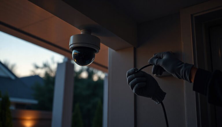
[…] safely connect a PoE CCTV camera, match the camera’s required PoE standard to the correct PoE switch/injector/NVR port, use environment-rated Ethernet cable, and keep power off while you make connections. […]