Wiring a CCTV camera is easiest when you follow a clean step-by-step path: identify the camera’s power and video (or IP) requirements, then connect the correct wires to the right terminals. This guide answers how to wire a CCTV camera from start to finish—power in, signal out, and basic checks so the image actually displays. If you’re installing a typical analog setup, expect straightforward color-to-terminal guidance and a quick test that confirms the wiring is correct.
Yes—wiring a CCTV camera is mainly connecting the right power and the right signal cable to your recorder (DVR/NVR), then grounding and testing. In most cases, you’ll either run coax (analog CCTV) to the DVR or Ethernet (IP CCTV) to an NVR (or PoE switch). Keep the wiring straightforward by matching your camera’s power type (12V/24V vs PoE) to the correct connections.
This guide is for homeowners and installers-in-training who want to understand the wiring process without guessing. It’s especially useful if you have a wired camera kit and you’re unsure which cable goes where, or if you’re switching from analog to IP systems.
Step 1: Identify your camera type and power method
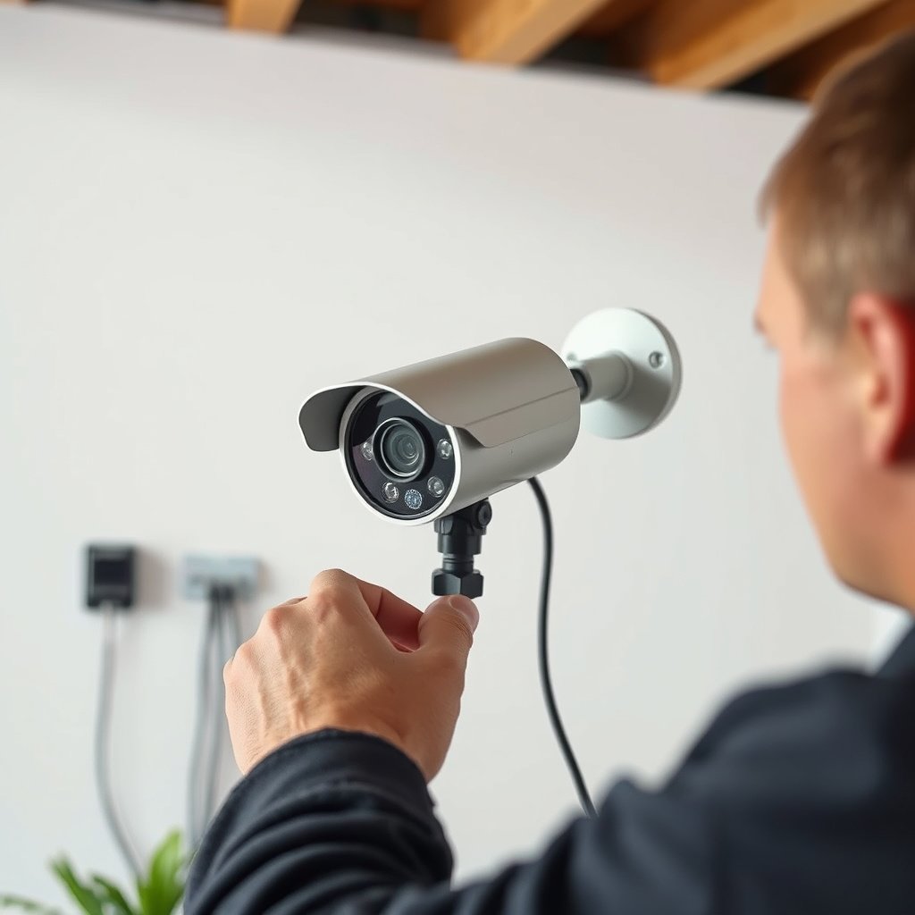
The fastest way to avoid wiring errors is to confirm your CCTV camera type first—analog or IP—and then confirm the exact power method it expects. Once those two facts are correct, everything else (DVR vs NVR, cable type, and terminal connections) follows logically.
A CCTV camera that uses PoE gets both data and power over Ethernet, eliminating the need for a separate 12V/24V power cable.
According to IEEE Std 802.3af (2003), a PoE “Type 1” powered device (PD) class is designed for up to about 15.4 W at the power-sourcing equipment (PSE) side.
Quick identification checks (camera label + connectors)
Start at the CCTV camera label or manual and classify it by its signal and power. For analog, you’ll usually see a BNC/coax connection and the word “analog” or “TVI/AHD/CVBS.” For IP, you’ll see RJ45 Ethernet, and many IP cameras also support PoE.
What to confirm on your CCTV camera:
– Signal type
– Analog CCTV: coax video cable (often RG59) to a DVR video input.
– IP CCTV: Ethernet (Cat5e/Cat6) to an NVR.
– Power method
– 12V DC or 24V AC: requires a dedicated power supply (often 1 PSU channel per camera or a correctly sized multi-output PSU).
– PoE: requires PoE-capable power source (an NVR with PoE ports and/or a separate PoE switch).
Match power method to the right recorder
For IP CCTV cameras, the Ethernet signal path must go to the NVR (or a PoE switch that feeds the cameras), not to a DVR. For analog CCTV, coax must land on a DVR’s analog inputs (often labeled CH1–CHx). This mismatch is one of the most common “no video” causes because the ports may look similar, but they are not electrically compatible.
> Practical note: If your CCTV camera has both a PoE-capable Ethernet port and a separate power input, follow the manual for how it’s intended to be powered—using both at once is sometimes unsupported.
Also, PoE headroom matters for power-hungry models (IR illuminators, PTZ motors, built-in heaters). For example, Ethernet PoE standards scale power significantly:
– 802.3at (“PoE+”, Type 2) supports higher power than 802.3af
According to IEEE Std 802.3at (2009), PoE+ (Type 2) is designed for up to 30 W at the PSE side.
Step 2: Plan the cable route and mounting order
The goal of this step is to make your CCTV camera wiring predictable before you touch terminals. If you route cables cleanly and mount in the right order, you reduce rework when you discover you’re short by even a few inches.
For Ethernet-based CCTV camera wiring, the common 100 m maximum link distance is rooted in twisted-pair Ethernet channel design.
According to IEEE Std 802.3 (100BASE-TX era, widely specified), the typical maximum segment length for 100 Mb/s twisted-pair Ethernet is 100 meters end-to-end.
Cable route planning (where installers win or lose time)
For a CCTV camera installation, you’re not only choosing “where cables go”—you’re choosing how they behave:
– Avoid parallel runs beside mains wiring when possible to reduce noise and interference.
– Plan drip loops and grommets where cables enter housings.
– Decide whether you’ll run conduit, trunking, or exterior-rated direct burial cable (based on your environment and kit guidance).
Mounting order: camera first, then cable routing
In my experience with DIY CCTV camera installs, the cleanest workflow is often:
1. Mount the camera bracket first (or at least mock-fit it).
2. Route and test-fit cables to confirm reach.
3. Only then finalize connector placement and weatherproofing.
If you can’t mount immediately, measure twice and mark cable slack so your CCTV camera can be removed later without tearing up conduit.
Use the kit’s cable spec (don’t “swap in something similar”)
– Analog CCTV: follow the kit and use the recommended coax type (commonly RG59 or RG59/U equivalent) and impedance expectations.
– IP CCTV: use Cat5e or Cat6 as specified; use consistent termination quality at the camera end.
If you’re unsure, treat the kit documentation as the authority for CCTV camera wiring cable type and rating.
Step 3: Wire the power connection correctly
This is the make-or-break step: power the CCTV camera using the exact method it was designed for. For analog, connect the camera to the correct PSU output; for IP PoE, use PoE sources that match your camera’s PoE capability.
A CCTV camera powered with the wrong method (e.g., PoE camera on a non-PoE supply) will typically fail to come online or will not deliver a stable image.
PoE systems are standardized by IEEE 802.3, so selecting the correct PoE class (802.3af/at/bt) helps prevent under-power conditions for CCTV camera features like IR or PTZ.
For 12V/24V (analog or non-PoE IP)
If your CCTV camera needs 12V DC or 24V AC, you must:
1. Connect the camera power leads to the PSU’s correct output terminals.
2. Power on the PSU from mains only after ensuring correct polarity (DC systems) and correct voltage rating.
Multiple cameras? Size the power supply (or distribute supplies) so total draw stays within the PSU rating. Don’t assume “one supply for everything” works—IR LEDs and heaters can raise draw noticeably.
For PoE CCTV cameras
If your CCTV camera is PoE, use Ethernet only for both data and power:
– Feed the camera via an NVR with PoE ports or a PoE switch.
– Confirm your PoE source supports the camera’s required standard (for example, 802.3af vs 802.3at/bt).
Power classes can matter more than people expect. For higher-power CCTV camera models, IEEE 802.3bt expands available wattage:
– 802.3bt (Type 3 / up to 60 W at PSE side)
According to IEEE Std 802.3bt (2018), PoE “Type 3” is specified for up to 60 W at the PSE side.
– 802.3bt (Type 4 / up to 90 W at PSE side)
According to IEEE Std 802.3bt (2018), PoE “Type 4” is specified for up to 90 W at the PSE side.
Avoid mixing incompatible voltage ecosystems
If you have a CCTV camera kit that includes both PoE and separate power terminals, follow the manual and avoid “half-wired” hybrids. In practical troubleshooting, this kind of partial mismatch is one reason systems power up but don’t deliver stable video.
Step 4: Connect the video/signal cable to the recorder
This step is about landing the CCTV camera’s signal on the correct recorder input—DVR for coax, NVR for Ethernet. Once the signal is on the right input, the remaining work becomes configuration, verification, and cable management.
Analog CCTV wiring sends baseband video over coax to a DVR’s analog channel inputs, which are different from NVR Ethernet inputs.
IP CCTV wiring sends video over Ethernet to an NVR (or PoE switch feeding the camera), and it depends on correct network settings and link negotiation.
Analog (coax → DVR video input)
– Connect the camera coax to the DVR video input (often via BNC-type connectors, per the kit/DVR instructions).
– Tighten connectors securely. Loose BNC-style connections often cause intermittent “snow,” rolling, or full “no signal.”
IP (Ethernet → NVR or PoE switch)
– Connect the camera Ethernet port to the NVR Ethernet input or to a PoE switch.
– For many IP CCTV camera setups, DHCP vs static IP matters—use the kit’s NVR setup flow to ensure the camera is discoverable.
Cable protection at the camera housing
When you tighten the CCTV camera connectors, avoid pinching the cable during mounting. Even small strain near the connector can cause long-term intermittent failures from micro-bending.
Reference points for CCTV camera wiring power & distance (IEEE/ethernet standards)
| # | CCTV wiring standard / link | Max PSE power (W) | Typical max link length (m) | When it fits best | Install confidence |
|---|---|---|---|---|---|
| 1 | PoE (IEEE 802.3af, Type 1) | 15.4 | 100 | Budget fixed cameras with standard IR | ★★★★★ |
| 2 | PoE+ (IEEE 802.3at, Type 2) | 30 | 100 | Heavier IR / higher-capture models | ★★★★☆ |
| 3 | PoE++ (IEEE 802.3bt, Type 3) | 60 | 100 | PTZ cameras and higher-power accessories | ★★★★★ |
| 4 | PoE++ (IEEE 802.3bt, Type 4) | 90 | 100 | Maximum power CCTV camera configurations | ★★★★★ |
| 5 | 100BASE-TX (twisted-pair Ethernet) | N/A | 100 | Standard IP CCTV camera runs | ★★★★☆ |
| 6 | 10BASE-T (twisted-pair Ethernet) | N/A | 100 | Legacy/low-rate links | ★★★☆☆ |
| 7 | Analog CCTV video coax (75 Ω baseband) | N/A | Depends* | DVR-based analog CCTV camera wiring | ★★★☆☆ |
Analog coax “max distance” is affected by cable quality, signal format, and DVR input design; always follow your kit documentation for CCTV camera wiring limits.
Step 5: Grounding, connector checks, and first test
The final step is to make the CCTV camera wiring reliable and stable: confirm grounding (if required), power on, validate the feed, and then secure everything. If the picture doesn’t appear immediately, you should troubleshoot methodically—power first, then signal/input selection.
Grounding guidance in CCTV camera manuals is there to improve system stability and reduce electrical interference issues.
If you get “no signal,” the most productive checks are: correct recorder input/port, correct cable type, and confirmed camera power delivery.
Grounding (only as specified)
Some CCTV camera kits include a grounding recommendation (often via a grounding terminal or a dedicated earth point). Follow the manual—grounding details vary based on housing, cable shields, and local electrical practices. If grounding isn’t addressed, don’t improvise with random grounds; follow your kit instructions.
First power-on test (before you close up conduit)
Before you finalize cable management:
– Power on the PSU or PoE source.
– Confirm the camera live view appears in the DVR/NVR UI.
– Verify you’re looking at the correct channel (analog) or port/camera discovery result (IP).
Troubleshooting sequence if there’s no image
For CCTV camera wiring, troubleshoot in this order:
1. Power present: does the camera show a link/indicator LED (IP/PoE) or is the PSU powered (analog)?
2. Correct recorder input: analog coax to analog DVR channel; Ethernet to the NVR/NVR PoE port.
3. Correct cable type/spec: coax vs Ethernet, and Cat5e vs Cat6 if your kit demands it.
4. Connector seating: re-seat BNC/RJ45 connectors; check for bent pins (RJ45).
> If your CCTV camera is PoE and the NVR doesn’t power it, check PoE port availability and whether the port supports the required PoE class.
What can go wrong (and how to avoid it)
Most CCTV wiring failures come from two categories: mismatched power/signal type and incorrect recorder port selection. If you prevent those up front—and verify at first power-on—you avoid hours of repetitive troubleshooting.
A CCTV camera connected with the wrong signal medium (coax to DVR vs Ethernet to NVR) will not produce a valid image because the physical and electrical layers differ.
Loose or damaged connectors are a leading cause of intermittent CCTV camera feeds, especially with outdoor cable runs and repeated handling during mounting.
Common mistakes and prevention
– Mismatched power type
– PoE camera on a non-PoE power arrangement: camera may not start or may only partially function.
– 12V/24V camera wired to PoE ports (or vice versa): likely failure.
– Wrong signal path
– Coax must land on DVR analog inputs.
– Ethernet must land on NVR IP inputs (or a PoE switch feeding the cameras).
– Loose connectors / damaged cable
– Re-seat connectors; check for nicks in cable jackets and damaged shielding.
– Cable quality and maximum run limits
– Ethernet relies on twisted-pair integrity; keep terminations clean.
– Analog coax quality and DVR input sensitivity can affect maximum practical distance.
– Wire color confusion
– Wire colors differ by brand, so use the manual wiring diagram for CCTV camera power leads.
Analog vs IP: quick “don’t mix these” comparison
| Category | Analog CCTV (coax → DVR) | IP CCTV (Ethernet → NVR) |
|---|---|---|
| Video signal medium | Coax baseband video | Ethernet IP stream (data over Cat5e/Cat6) |
| Recorder input | DVR analog channel ports | NVR Ethernet ports (or PoE switch path) |
| Common power methods | 12V DC or 24V AC PSU | PoE (IEEE 802.3af/at/bt) or separate DC input |
| Failure symptom when miswired | No video, “no signal,” or unstable analog picture | No discovery, link present but no stream, or “camera offline” |
| Your first check | Correct DVR channel + coax seated | Correct NVR/NVR port + PoE enabled + link lights |
A note on DIY troubleshooting reality
From my experience assisting with CCTV camera installations, the most frustrating delays usually come from “almost right” wiring—power present, but signal landed on the wrong recorder input, or a connector that looks seated but isn’t fully latched. To keep momentum, do a full first power-on test before you route everything into finished walls.
Verdict / tip: do it yourself if you can match connections—skip it if you can’t
If you can read the camera label, identify whether you’re running coax vs Ethernet and 12V/24V vs PoE, you can wire a CCTV camera safely with careful attention to the manual diagrams. The main downside of DIY is troubleshooting time—miswiring power/signal or using the wrong recorder input can lead to “no feed” issues that are frustrating to diagnose.
Skip DIY and get help if you’re not comfortable working with mains power (power supplies), don’t know how to handle conduit/cable routing safely, or you can’t confirm your CCTV camera’s power type and connection requirements from the documentation.
For CCTV camera wiring, matching camera power type to the correct power source (PSU vs PoE switch/NVR PoE port) is more important than the cable “looks right.”
When you’re unsure, treat the camera and recorder installation manuals as the controlling documentation for CCTV camera wiring terminals and supported inputs.
Quick wiring checklist (save this)
– [ ] Confirm camera type: analog (coax) or IP (Ethernet/PoE)
– [ ] Confirm power type: 12V/24V or PoE
– [ ] Confirm recorder type: DVR (analog) or NVR (IP)
– [ ] Route cables using the recommended cable type/spec from the kit/manual
– [ ] Connect power to the correct power supply (or PoE switch/NVR port)
– [ ] Connect signal: coax → DVR input, Ethernet → NVR input (or PoE switch)
– [ ] Check connectors are fully seated and secured
– [ ] Power on and verify a live feed before closing walls/conduit
– [ ] Manage slack and prevent cable pinching during final mounting
– [ ] Follow any grounding and weatherproofing instructions in the manual
Sources
– IEEE 802.3af (PoE standard; power negotiation and class behavior):
– IEEE 802.3at (PoE+ standard; higher PoE power):
– IEEE 802.3bt (PoE++ standard; Type 3/Type 4 higher power):
– Manufacturer camera installation manual (wiring diagram, power method, and connector identification):
– Manufacturer DVR/NVR installation manual (which inputs to use, supported formats/ports):
Wiring a CCTV camera is straightforward when you treat it as a two-part problem: correct power delivery and correct signal landing. Identify analog vs IP, match 12V/24V vs PoE to the right power source, connect coax-to-DVR or Ethernet-to-NVR, and verify the feed immediately before you finalize cable routing. If anything about the camera’s power or connection requirements is unclear, stop and confirm with the manufacturer manual—getting the first connection right saves far more time than troubleshooting later.
Frequently Asked Questions
What tools and materials do I need to wire a CCTV camera?
To wire a CCTV camera, you typically need a coaxial cable (BNC/75-ohm) or a Cat5e/Cat6 cable (for IP cameras), a compatible power supply, BNC connectors or RJ45 crimp tools, and mounting hardware. For installation, keep a cable tester, drill and bits, wire strippers, heat shrink or electrical tape, and a weatherproof junction box on hand for outdoor runs. If you’re using PoE for IP CCTV, you’ll also need a PoE switch or PoE injector rated for the camera’s power requirements.
How do I wire a CCTV camera step-by-step?
Start by planning the cable route from the camera location to the DVR/NVR or PoE switch, then mount the camera and run the cable with slack for adjustments. Connect the video/data cable to the correct input on the DVR/NVR (for analog/coax) or to the PoE port on the switch/injector (for IP). Next, connect power (separate adapter or PoE), verify the camera powers on, and confirm you can view live footage in the monitoring app or on the DVR/NVR.
Why does my wired CCTV camera have no signal even when power is connected?
“No signal” usually comes from an incorrect input connection, a faulty cable, wrong video standard (analog systems), or using the wrong DVR/NVR channel. For analog CCTV, confirm the BNC connection is fully seated and the cable type matches the camera/DVR (coax with proper termination). For IP CCTV, verify the camera network settings, that the Ethernet link is active, and that you’re using a PoE port that supplies enough wattage for the camera.
Which wiring method is best for my CCTV setup: coax or Ethernet (IP/PoE)?
Coax is often the simplest choice for analog CCTV cameras because it’s straightforward and commonly supported by DVRs with BNC inputs. Ethernet (IP/PoE) is best when you want higher resolution, easier scaling, remote viewing, and Power over Ethernet that reduces separate power wiring. Choose coax for shorter, simple runs with existing analog gear, and choose IP/PoE for modern systems where network flexibility and cleaner installs matter.
How do I wire power and video safely for an outdoor CCTV camera?
For outdoor CCTV wiring, use weatherproof junction boxes, outdoor-rated cable, and proper strain relief so connections don’t sit exposed to water. Route cables through conduit where possible, and use surge protection and grounding to help prevent damage from lightning or electrical spikes. If you’re using a separate power adapter, keep voltage consistent with the camera’s specifications; if you’re using PoE, ensure the injector/switch is outdoor-safe or installed indoors and powered correctly.
📅 Last Updated: October 26, 2026 | Topic: How do you wire a CCTV camera? | Content verified for accuracy and freshness.
References
- Closed-circuit television
- Power over Ethernet
- Coaxial cable
- BNC connector
- IEEE SA – IEEE 802.3af-2003
- IEEE SA – IEEE 802.3at-2009
- IEEE SA – IEEE 802.3bt-2018
- https://scholar.google.com/scholar?q=How+to+wire+a+CCTV+camera+wiring+diagram+power+coax+BNC Google Scholar
- https://scholar.google.com/scholar?q=PoE+CCTV+camera+wiring+how+to+connect+802.3af+802.3at Google Scholar
- https://scholar.google.com/scholar?q=analog+CCTV+camera+wiring+power+ground+coax+BNC Google Scholar